That will only work if the input “O/I” is high enough to trigger the reset…
If it’s close to 0V it won’t.
But that could add some randomness to the number of steps, it’s worth a try !
1 Like
Yeah, only stuck in 4 mode for about 24 hours…and I won’t have time to play with it in that time anyway 
It seemed natural to go with the divider, they’re both based on circuits from Fonitronik, and like you said they can work in tandem in some neat ways.
I did think about trying to patch one of the outputs to the reset…but was tired and didn’t feel like grabbing another patch cord to give it a try last night. That’s basically all the switch is doing anyway so seems like it should work.
No.
The (mechanical) switch is using the logical signal used by the electronic switches to connect one of the outputs to the input (or the other way, 4 in/1 out, the module is “reversible”).
1 Like
In an other thread I decided to add buffers on an old module.
One of the first module I did, I added 2 TL074 on the back. (I had room on the small wooden board that I had added to hold the recovery jacks without screws).
I took the opportunity to add indicator LEDs for the 2 LFOs and also add a 10K trimpot in place of the resistance of the led of my homemade vactrol for better adjustment.


9 Likes
got a DIY GEWEI kinda sorta working.

Response tweaks yet to come. lol
7 Likes
I LOVE the faders !! Always potis is so boring 
4 Likes


Had a re-jig of modules.
Left spaces for a couple I’ve got to finish like the CB55 and clock divider
6 Likes
I have to wait for a few more jacks to come in the mail,
But still I thought I’d collect my award for the laziest Kosmo conversion of all time

12 Likes
I started experimenting with an envelope follower designed by Harry Bissell as described here.

I got it to work but had to change capacitor C3 to get smooth envelopes ( if you follow the muffwiggler thread, which I did after bread boarding the circuit, you’ll find that other people suggest a similar change to the circuit ).

As you can see, the yellow line follows the blue signal’s contour quite well. I think I will make a selection switch so that I can vary the ‘smoothing’ capacitor.

Of course, your mileage may vary depending on the input signal.
B.t.w. if you change the diodes in the rectifiers of the peak detectors into LEDs, you can get a nice shimmering light from them.
6 Likes
I made an arduino based 6ch gate sequencer.
Chinese OLED is cheap and convenient.
However, due to the performance limitations of arduino, there are some restrictions.
for example : display update frequency


17 Likes
Looks Great!
I’m wondering which graphics library you are using and whether the rotary encoder is interrupt based. Have you encountered problems with the encoder interrupts interfering with the graphics library?
1 Like
@HAGIWO I checked your YouTube, very, very good indeed! I am quite interested in the Yamaha FM module, unfortunately I have not yet found out how and where I can get this chip. I have to deal with it again.
1 Like
Good work! Interface design is clear and not bloated!
1 Like
On muffwiggler Harry Bissell suggested to use a full wave rectifier as an input stage to his envelope follower. When contemplating to try this I thought: but then the signal is rectified by this new input stage AND the 1st op-amp in the peak detector. This makes it possible to maybe simplify the original design by leaving out the rectifying op-amp stages of the peak detectors. I tried this on a bread board and it works nicely. So this saves 3 opamps and produces the same results. I pimped the signal a bit by adding some gain to the output stages of the peak detectors. The signal processing part of the schematic can thus be reduced to:

Which results in the same envelope as the initial approach.

Note: the picture shows the envelope when I was experimenting with 1 simplified peak detector (the others were not connected) so the end result could be smoother.
To make the schematic complete you have to add the 40106 and 4017 circuit as shown in the original schematic.
6 Likes
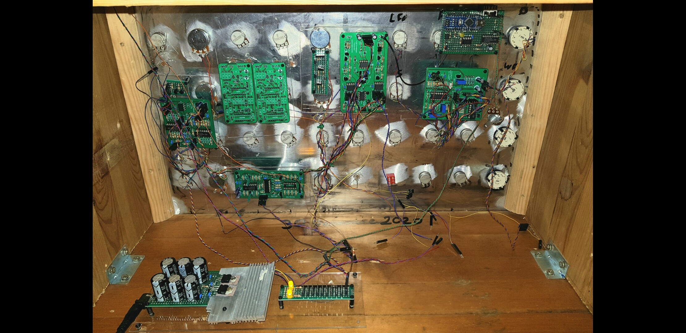
Some modification to my sequencer arduino panel for add the rotary switch of the new version.
2 Likes
Another PT2399 delay finished and foils printed for it and the other finished panels. I’m such a graphic noob, I have enough ideas for great panels, but the implementation doesn’t work at all.


For today I will finish work first, tomorrow I will have to stick a Steiner Parker and an MS20 filter panel and wire another Steiner Parker.
I also have to come up with something, the film is very sensitive, I probably need a layer of clear varnish over it. The next projects are the MFOS Wave Animator, dual Buchla LPG, MFOS stereo auto panner, tube screamer distortion and I’m still waiting for 3 pots for the Erica Synths polivoks ADSR.
When these modules are ready, my rack is also full and I can finally build the next one in KOSMO format! It’s really a pain in the ass to get all the crap on these little Eurorack panels and then you have to use these tiny potentiometer knobs. But I’m not sure yet whether I use 6.35mm jacks or just stick to 3.5mm, we’ll see. I also absolutely need a ring modulator, does anyone have a stripboard layout for that?
I successfully soldered my first SMD practice boards, so nothing stands in the way of Clouds.
7 Likes
I’ve made one stripboard for an Active Real Ring Modulator (CGS67 Ken Stone), not yet tested but if you want to try it on breadboard i can post it.
It’s a real ring modulator with diode and transfo
4 Likes
I would prefer a ring modulator that works, is simple and does not require any unusual components. If he could also clean my apartment and cook, it would be very nice
2 Likes
So far, I haven’t had any interrupt issues.
I didn’t think deeply, but I need interrupt care.
Thanks!
1 Like