Do you have a requirement for us based companies? Tayda is my go to.
2 Likes
Not particularly. I was just thinking about ship times.
1 Like
Agree w/@Caustic I get everything I can from tayda first then mouser for stuff they don’t have. The shipping is fast!
For mega drone I think you have to get a part or two from mouser
5 Likes
You can check our post on the Cheap Components thread:
Let us know if you have trouble finding anything not found in that post and we can see whats needed.
7 Likes
just finished building my two modules. how do you trim these?
i used these caps:
module 1 - 10x 47uF, 10x 22 uF
module 2 - 10x 10uF, 3x 4.7uF, 2x 2.2uF
the 47uF are quite low when the master tuning is not set fully clockwise. is that something you can adjust with the trimmers? or is there a reference voltage somewhere that i am missing?
1 Like
The cap determines the frequency, switch the 47uf to something smaller
i am aware of that. i will keep the 47uF, because i like the sound. was just wondering what the trimmer does.
The trimmer is a “starve” it adjusts how much or how little CV is allowed thru. Basically just a fine tuner
2 Likes
I just finished my megdrone kit, and I added a cap
switch.


Now i can hot swap between 2 cap sizes. I went with 2.2 and 10 uf
Too bad it’s already past 10 here on the East coast. I’ve only got a few more minutes to jam it though the PA before my wife tells me to turn it down
15 Likes
Nice! Great idea and it looks right at home.
2 Likes
Thanks.
I took some time off to focus on the synth. I put in ~40 hours over the last 4 days… But there’s still so much to do!
4 Likes

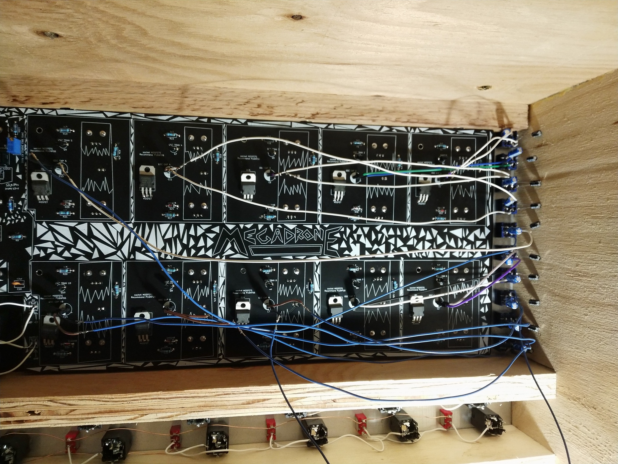
Drone update:
The extention panel escalated a little, but the module feels much more usable and I consider it finished (for now).

Like previously mentioned, each of the 24 oscillators can be isolated via the dip switches for better tuning.
The oscillators form 8 groups of 3. The blue pots set the level for the 8 individual outputs.
- The green buttons can sum up OUT 1-4 and OUT 5-8.
- At the same time they mute the respective individual output.
- The 2 black pots are combined hi-cut/lo-cut filters for the 2 group outputs.

I’ll draw a schematic of this whole mess and post it here later.
Although everything works, I’d like to hear your comments and suggestions.
What I noticed while adjusting the levels is that there are a lot of spikes in the waveform, so I may need to add some decoupling capacitors here and there.
11 Likes
I really cant get over how good this looks. This thing is really turning out very well.
3 Likes
yes it look very nice ! 
4 Likes
one of my oscillators does not react to the master tune knob. it does react to the cv input and it’s own tuning knob however. any idea what’s wrong?
1 Like
Points right at the mosfet I think.
1 Like
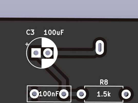
For the capacitors in C3, C8, and C9, am I correct in understanding that the short leg (marked by a white stripe on the cap) goes into the white section of the marked circle? The black is marked positive, so I’m sure that is right, but I just saw this video of the Atari Punk build Sam did, where he says the black is the negative side, so second guessing myself.

2 Likes
That’s because it uses a white PCB with black silkscreen, so everything is reversed…
1 Like
At JLCPCB two of the options are black solder mask
and white solder mask

You see the problem. The - side is the “filled” side, but whether that’s black or white depends on the solder mask and silkscreen colors, and it’s easy to get it wrong if you’re going by the “white”/“black” section and not paying enough attention.
There’s a + sign here which is unambiguous. Go by that. Also the + solder pad is square, but that could vary between footprint designs. (And as discussed here not too long ago, for LEDs the standard KiCad footprint has the square pad for the - side, confusingly.)
6 Likes