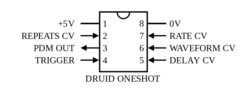
…so to power it up you need to set delay to a high value, press and hold trigger, and the output will then be connected to ground via a 1k resistor and the rate pot, which is safe.
can someone tell me what the switch is supposed to do? my one doesn’t seem to do anything, or maybe I put the wrong type in. its supposed to bed momentary (on/off/on) yes? otherwise it works perfectly
hmm thats weird im trying to think of instances when it wouldn’t work I am really not sure. only thing I can think is to check the soldering on the switch thats the only thing that would mean it doesn’t work, if its receiving triggers from the trigger in that is
A Saturday morning screw-up - soldered all 7 jack sockets to the wrong side of the board.
My mind is melting trying to square up the schematics with wrongly-connected sockets - I need some help figuring out if I can correct this using some cunning re-routing of the connector between the main board and the socket-board.
I’m highly discinclined to de-solder them all… and I suspect the board will flake out if I try!
And I know this ought to go in the litany of dumb-assery… and I’ll post there too once I’ve sorted it!
and you can see if you put it on the wrong side the sleeve terminal remains in the correct position and the tip terminal ends up in the place of the ring terminal and vice versa. None of the other terminals should connect to anything. So… you would have to connect a wire from the actual tip terminal to go to the main board. You could cut the tip terminal traces to the pin header footprint and run the wires to there, or just run the wires direct to the main board. If the latter then you’d also need to run a wire connecting the grounds of the two boards. Connections on the pin header are
aaaah damn!!! happens from time to time! indeed with a squeeze they can be put in backwards with the symbol for the jacks on the back, if you manage to not get it clean off let me know if im in a posting kind of day I will post one a spare jack board to you. just message me your address however if you manage to fix it it’ll be all good! but do give it a go first! but if it gets to the point it isn’t working just let me know
good luck
They’re now connected to your sleeve terminals, which when you plug in the cable will connect to ground, so they won’t do you any good. So you’ll have to add new resistors in series. I’d just solder them to the tip terminals and then wire from there to the main board.
You can in theory get by without the 1k output resistors, they’re just making the outputs more robust but the circuit will work without them, but if you leave out the 10k you risk frying the trigger transistor, and without the 200k resistors the CV inputs won’t work. So as @analogoutput said, solder one end to the tip and one to the wire, and you’re all set.
check the soldering on the rate potentiometer. it sounds like its at max speed all the time. so double check the leg of the rate potentiometer going to ground, As if this is not making a connection it will be on max all of the time
also to add are you directly listening to the output of the bounce module>? or is that modulating something like an oscillator?
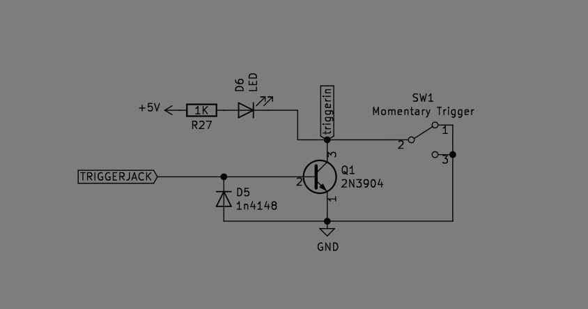
Hey, I just built this module, if i trigger manually with the button it works, if i put a gate on it from my vclfo i have +5 Volts on the jack board but on the mainboard it is only 0.50V.
The module also does not trigger from a gate and i guess the trigger voltage should be higher on the mainboard, i doe not see any bad solder joints or bridges, also no magic smoke.
i have directly soldered 2 wires from the mainboard to the jackboard, but still if i trigger with my lfo the voltage reads max of + 0.50 volts.
I have ZERO Volts at the trigger input…
I Have +0.50 Volts at the middle pin of the 2n3904, But nothing comes out
Anybody have any idea where to look for component wise for a problem or something because i cant seem to get it figured out…
have you checked the continuity between the jack board and main board?? each of the pins for instance??? maybe there is a connection not being made on the pcb headers???