Hello everyone,
I’m usually just lurking around, sometimes asking for help if I’m stuck and don’t know what to do. I recently built a gate pattern looper that some of you may find interesting. I haven’t found any post covering such a module, so here you go.
4031 Gate Looper
This is a 64-step gate/trigger sequencer (or looper) built around the CD4031, a 64-stage shift register.
An Arduino-less big button-ish module; less fancy and has fewer functions but more DIY (in my opinion), and no coding is required.
The module is based on Kristian Blasol’s schematics. See the original schematic here (Dropbox) and watch Kristian’s video here (Youtube).
Note: Kristian’s design itself is based on a schematic of Tiny Dazzler/Magic Pulsewave, which you can find here (Dropbox)
I somewhat modified the circuit, see the details below. I haven’t breadboarded this before the build, and I’m not an expert: I only have experience with electronics through DIY synth. The module works, but some stuff might be improved.
1. Schematic
This is my modified schematic:
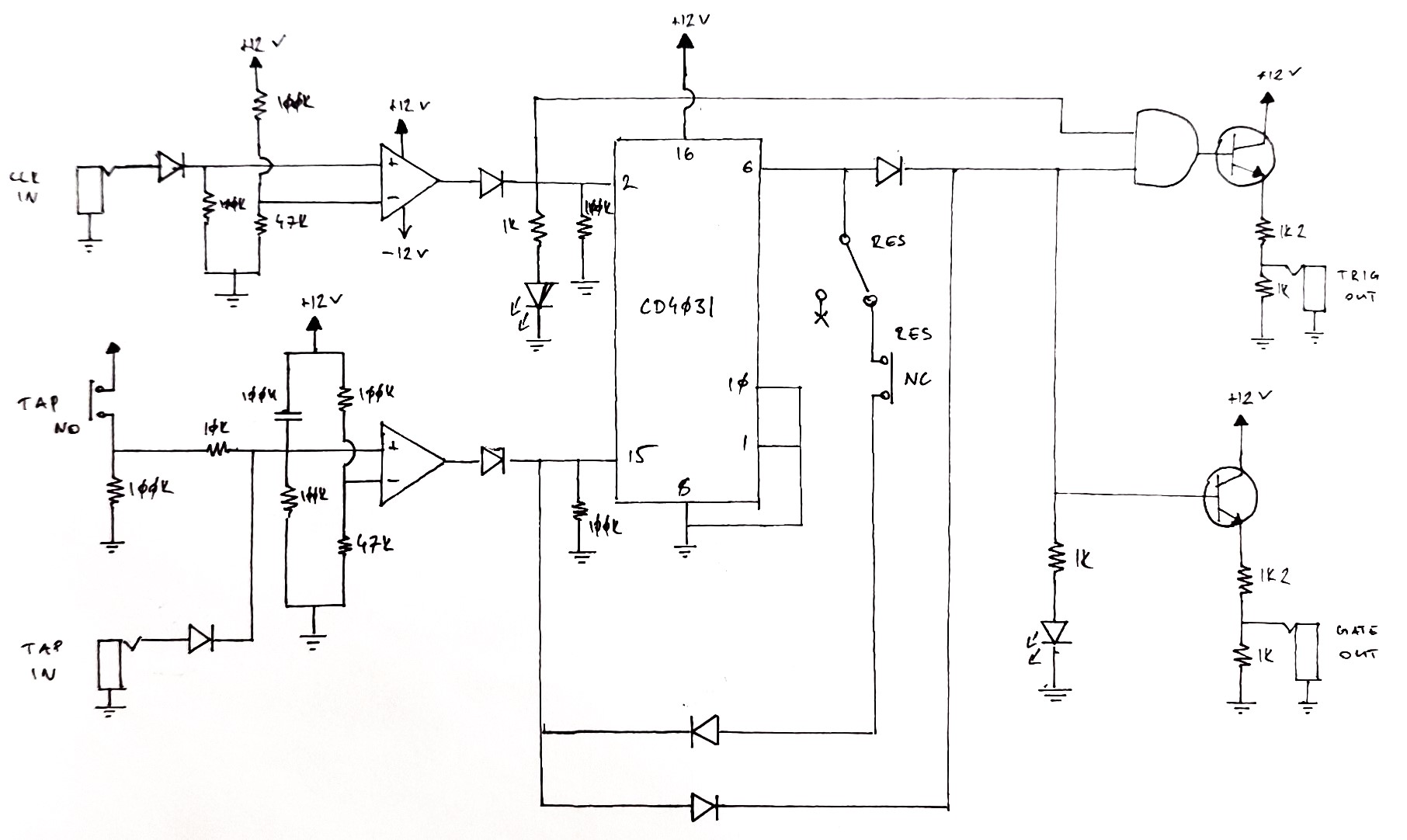
4031 Gate Looper schematic
All semiconductors are general-purpose components, nothing fancy is needed:
- 1N4148 for diodes (except LEDs)
- BC547 (or 2N3904) for transistors
- TL07x for op-amps
The reset wiring could be tricky, see the explanation below (under Limitations)
No calibration is needed.
1.2 List of modifications
These are the modifications I implemented (see the labeled schematic below):
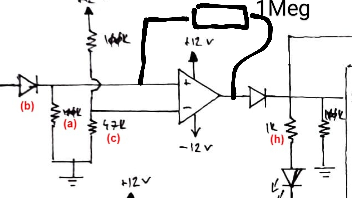
(a) Add a 100K resistor to GND before both op-amp V+ for input impedance
(b) Add a diode in series before both op-amp V+ for reverse polarity protection
(c) Replace 1k resistor to GND with 47k in the voltage dividers before both op-amp V- for a better functioning comparator (so the minimum input is raised to +3.84V instead of +0.12V – which was too small in my opinion)
(d) Connect buffered input to the output stage via a diode to include tap/in as direct output
(e) Add a diode after the Reset stage to protect 4031 Q (pin 6) and DIN (pin 15) from the tap input
(f) Rework output stage
(g) Add gate buffer for CMOS output protection (Ken Stone-style)
(h) Replace 10k current limiting resistors before LEDs with 1k (maybe this isn’t necessary, I was afraid the LEDs won’t be shiny enough)
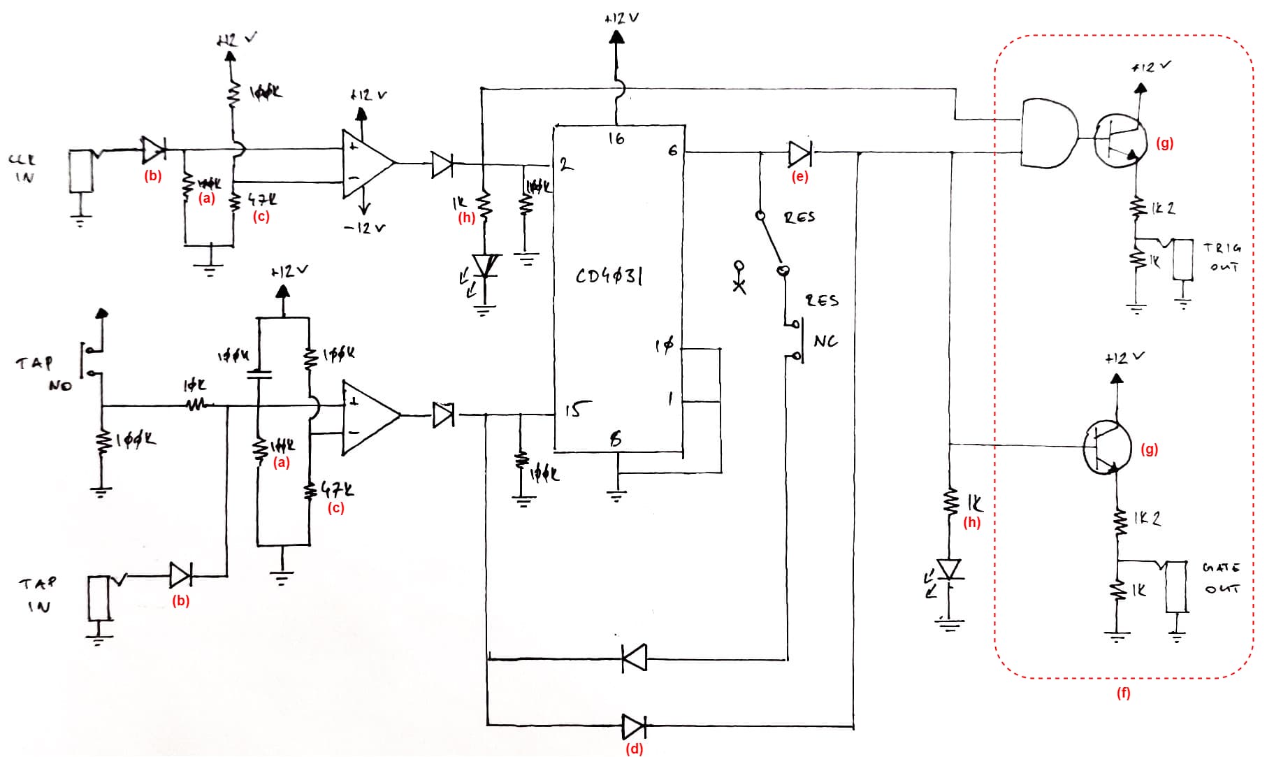
4031 Gate Looper schematic with modification labels
2. Usage
In a nutshell: to record a pattern, connect a clock input to CLK IN, then tap in the pattern via the TAP button or the TAP IN jack.
Front panel description:
| Component | Type | Explanation |
|---|---|---|
| CLK IN | Input | A jack for the clock input. Around +5V is enough. |
| CLK LED | Indicator | An LED indicating if CLK IN is high. |
| TAP (MOM) | Input | A momentary switch for manual DATA input. |
| TAP IN | Input | A jack for external DATA input. Can be used to record preset patterns (e.g., a sequenced gate pattern) or input from external triggers, e.g., a piezo drum trigger. Around +5V is enough. |
| GATE LED | Indicator | An LED indicating if GATE OUT is high. |
| TRIG OUT | Output | A jack for the trigger output. The trigger is basically the chopped-up version of the gate output: it is high if the CLK IN and GATE OUT are both high; i.e., if both the CLK LED and the GATE LED are illuminated. |
| GATE OUT | Output | A jack for the gate output. The gate is continuously sent as long as the GATE LED is illuminated. |
| RES | Input | A switch for resetting the memory. The memory is only reset for the next cycle. See the explanation under Limitations. |
| RES (MOM) | Input | A push button for resetting the memory. The memory is only reset for the next cycle. See the explanation under Limitations. |
Further information:
The TRIG OUT and GATE OUT level is defined by the voltage dividers in the output buffer stage. With a ±12V PSU, the output should be around +5.4V (I haven’t yet measured though). If using a ±15V PSU, or a different output level is needed, adjust the values.
If the CLK LED or the GATE LED is not illuminated, the input level is probably too low. CLK IN and TAP are both set up to work with +5V inputs. If using a ±15 PSU, or working with lower input levels, adjust the values of the voltage divider before V- of the op-amps. Consider the input voltage drop due to the diode.
3. Limitations
3.1 Recorded gate/trigger is not excluded immediately upon reset
One bit of memory is reset if 4031 Q (pin 6) is not sent back to DIN (pin 15); i.e., the reset switches should be wired so that the feedback is not broken by default (this is why an NC MOM switch is required). If the reset switch is flicked open or the MOM is pushed, the actual bit of memory is reset to low, but the gate is still included in the output. This also means that if the reset switch is flicked open, the whole memory is reset after one cycle.
So there is room for improvement. E.g., the output could be connected to GND if the reset is engaged; so the reset functions immediately (by excluding the gate from the output). This could be solved with a couple of extra components. The switch reset can be replaced with a simple DPDT switch that cuts the output (and leads to GND), so that would work as a reset + mute switch; see the image below. (Thinking of this, maybe I’ll replace the switches in my build too.)
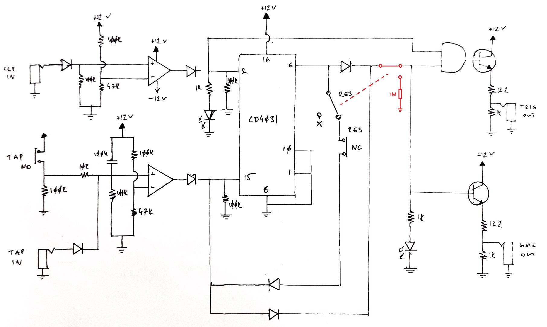
Reset + Mute modification
The problem of the push button would still be there. Maybe an OFF-ON-(OFF) DP3T switch, is there such a thing?
3.2 64-step limit
The module can only process 64 bits: no less and no more. This means that only 64-step-long patterns can be recorded.
However, a clock divider in the patch can do some wizardry. E.g., using a fast clock to drive the 4031 looper and the CLK/4 out for driving a sequence leads to 16-step long gate sequences (and the trigger output will be funny, what a feature). Still, no unusual sequence length can be set; e.g., 64 cannot be divided with 3, 5, 7… you can do the math.
3.3 Precision
The tap input requires some practice, but I don’t think it’s impossible to master. Also, the TAP IN can be used to record precise taps from a sequencer.
4. Build recommendations
I built a quad looper; i.e., the schematic above four times, with some common components. Some notes for that:
- 2 × TL074 were used for the comparators
- 1 × CD4081 is used for all the AND gates
- A push button with an integrated LED is used for the manual tap input; its LED is used for the gate output LED
- The CLK input is chained using the jack switches (A > B > C > D).
The Reset + Mute mod could worth a try too.
5. Impression and example use cases
I find the 4031 gate looper very versatile and easy to use. It could be used to record gate or “chopped up” trigger patterns easily during a live performance. Just don’t forget to start the memory reset before the last cycle or just mute the channel it is driving. Here are some use cases for example.
-
Drum trigger: Maybe the most general application is to use the gate/trigger output as the trigger for different drum modules (or percussive bass). See this video (Google Drive) for an example (not the best quality, but you get the idea; the same clock is used for all the loopers.) You can use the trigger out for chopped-up hi-hats. Also, connect piezo drum triggers to the TAP IN and now you have a fancy drum tap looper.
-
Sequencer pattern: Set the clock of a sequencer; i.e., use different note lengths for the steps. You could play with the number of gates in the 4031 loop and the number of steps of the sequencer to get unusual patterns (e.g., 13 taps vs. a 7-step sequence).
-
Broken chord patterns: Use the gate output to trigger four different EGs to open particular VCAs of individual VCOs.
This is how I used my freshly built module but I’m sure there are other use cases.