I started building the Halting Problem, but then discovered either my spreadsheet is lying to me again or I’ve misplaced 15 or so 50k potentiometers, so I had to stop.
Which is either appropriate or ironic, when you think about it.
I started building the Halting Problem, but then discovered either my spreadsheet is lying to me again or I’ve misplaced 15 or so 50k potentiometers, so I had to stop.
Which is either appropriate or ironic, when you think about it.
I ran into a paper named Random Sequencer Documentation by Tom Whitwell, and read it thru and got more and more confused as I understood that this must be the (original??) Turing Machine.
Reading thru and checking the schematics, I understood that the design is very simple and I’d definitly am prepared to try it out.
I notice that this Machine is based on two 8-step shiftregisters but does the length of the second one matter? I mean a 4006 has 18 stages, a 4031 or a 4517 each have 64 stages.
Also does the choise of DA-converter play any major role? A simple R-2R could possibly do and, even if I think I have a DAC0800, I have some of Ferranti’s simple-to-use DACs.
I really love the idea of modules creating regenerative music and I am about to finish Ken Stone’s iNfinity Music module, which is, as I get it a sort of inverted Turing Machine.
On the drawing board is an 8-step sequencer where the counter (w presets) can be overtaken by a pseudo-random noise generator much like Ray Wilson’s 32-step sequencer.
Doesn’t turn up when I Google it, what is it?
Here it is:
CGS32 Infinite Melody.
It differs in that “quantized” noised is the data clocked into the SR and not determine what data is to be clocked.
I love it because it has loads more of knobs and buttons … ![]()
![]()
![]()
Mine seems to be working! At least at some level. Trimmer might need a bit more tweaking and I need to look more carefully at the outputs but it seems good.
Mine is based off @sebastian’s version; changes are mostly stylistic:
More substantively (though still minor):
I’m using the “super low current” (a.k.a. “super bright”) LEDs with 150k resistors to minimize whacking the power rail around.
Github repo for my fork here:
If anyone’s interested in boards and panels I have a few, DM me and we’ll work it out.
Thanks, @sebastian and @BenRufenacht and Tom Whitwell!
I’m having trouble with the lock control of the module, it doesn’t seem to lock with i turn CHANGE1 all the way to the right.
I’ve checked the continuity from CHANGE1 through the resistors to the + and - 12v. As well as to IC1A (the TL072) and from that to the SWITCH_IC1C and it all seems to be connected.
I also tried replacing the TL072.
Everything else appears to be working, and it’s a lot of fun but i can’t seem to lock a sequence, just have random sequences all the time ![]()
Also wondering how to set the trimmer to the correct value.
Here is a video of it running on length 2 and length 8 sequences:

Any help appreciated!
There’s a white noise source and when the noise goes above a threshold it flips the bit being cycled back from the end of the shift register to the beginning, if it is below the threshold it doesn’t flip the bit. Or maybe vice versa, I don’t remember. The big knob controls the threshold. (And the CV in but let’s assume that is unplugged.) When it’s all the way to the right the noise is always below threshold so nothing ever gets flipped and the sequence is locked; when it’s all the way to the left the noise is always above threshold so everything gets flipped and the sequence followed by the inverted sequence is locked; when it’s centered the noise is above threshold half the time and below half the time, so everything is equally likely to be flipped or not and the sequence is totally random.
For this to work the maximum noise amplitude has to be near but below the maximum threshold and similarly for the minimum. The trimmer varies the gain of the amplifier on the noise. So it should be set so the sequence locks at the ends but changes when the knob is closer to the middle.
The noise gets sent to the noise out jack, so if you have a scope you can look at it and see if the amplitude is small enough. The minimum/maximum thresholds are about ±8.6 V.
Assuming the trimmer is working you should definitely be able to dial the noise amplifier gain right down to 0 at which point it should be about impossible NOT to lock. If the noise amplitude is very low and it’s still not locking then check the voltage at TL072 pin 7 — should always be either + or - about 10.5 V depending on whether the knob is left or right. On the other side of the 100k resistor (R5) it should be either +10.6 V or about 0 V (or a little negative). Same at pins 6 and 13 of the 4016. Pins 3 and 9 should connect to ground. Of course TL072 pin 4 should be -12 V, pin 8 should be + 12 V; 4016 pin 14 should be +12 V and pin 7 should be ground.
If the noise amplitude cannot be made small then check the TL074 and R22–24, R29.
Thanks so much! I think I have it working! but with caveats
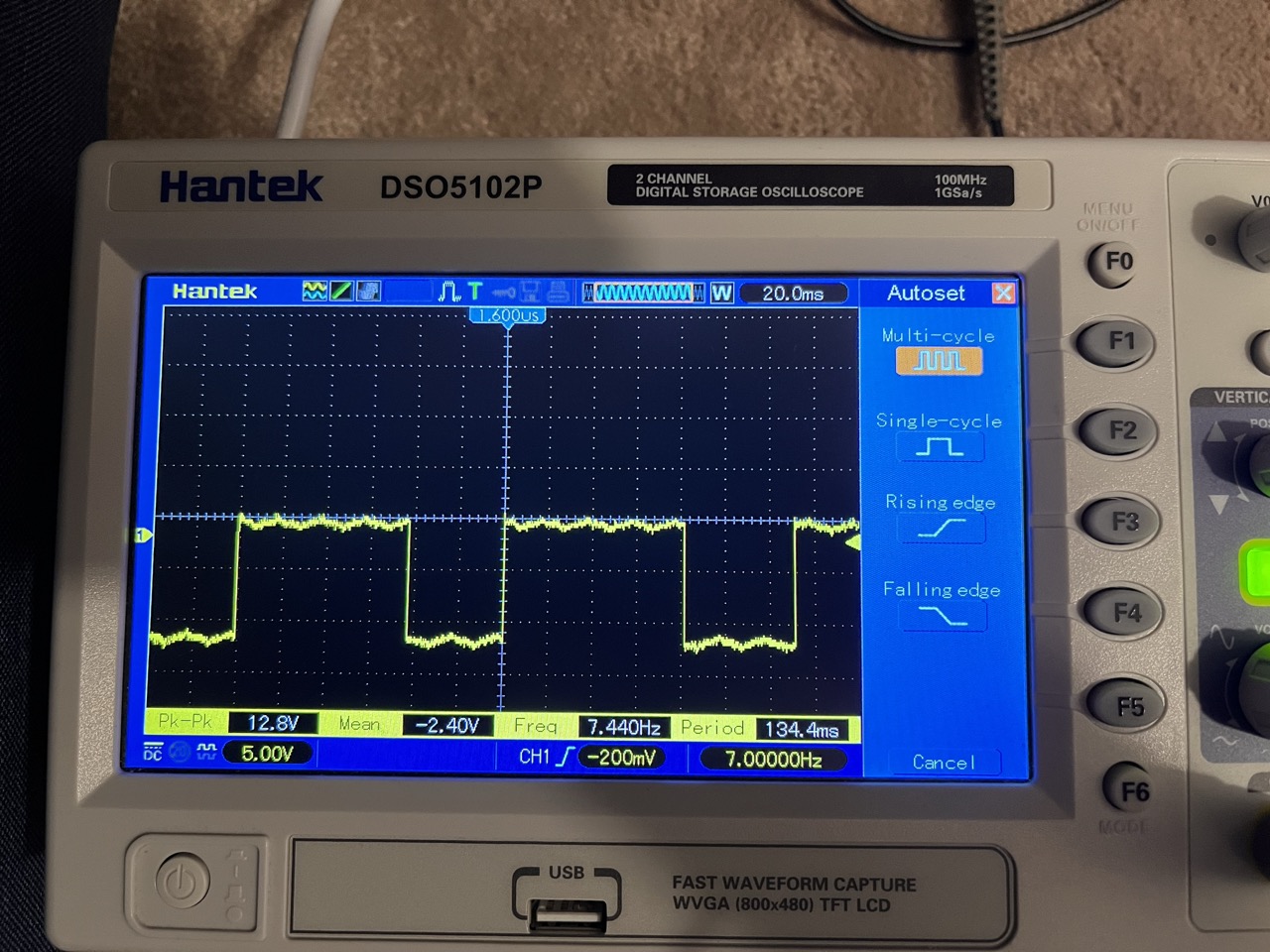
This helped a lot, I hooked the noise up to my scope, it’s an old one so im not sure if im reading the values right. I turned the trimmer way down and when it stopped visually clipping in the scope it seems to change it, i then got it to a stage where the locked side locks and above that it lets in an ammout of random that seems right.
Though trying to see what the values are in the scope it seems like the voltage is +/- 0.2v I’m guessing I’m reading the scope wrong or it’s not calibrated or something as the module feels like it’s working properly ![]()
Here is the scope set to 0.5v per division (i think that means the solid lines)
Thanks so much!
Just want to double check the connection naming on the Halting Problem (based on Turing Machine) and expanders, is this right?
Potentials (based on Volts)
Connects to Gates 1 on Halting Problem
HP Gates (based on Pulses)
Connects to Pulses 1 on Halting Problem
Basically want to make sure “HP Gates” doesn’t connect to “Gates 1” right?
Either can connect to either.
“HP Gates” was probably not the best choice of name, but arguably “Pulses” wasn’t either. I think connecting either way is fine, giving different results (gates that stay on until they turn off, or sequences of shorter gates with off periods between).

With a modification to the panel you presumably could add the daughterboard from @clarionut’s LPG-Mix to make the connection switch selectable.
But Potentials to Gates as opposed to Pulses would be more typical use for that one.
Naming is the hardest problem in computer science
Thanks for clarifying, the switchable panel could be really cool!
Yeah, I took a closer look… trouble is there isn’t room on the panel that isn’t blocked by the PCB for the switch and jack. So one would have to do some kind of major layout revision, or else just make the panel 25 mm wider.
(Wait, just realized… you probably could fit the switch without the jack. You wouldn’t have the ability to switch using a gate, but that’s not such a huge loss I think.)
My original idea for the Pulses/Gates selector add-on was that it would just be controlled by a switch, so that sounds like a good compromise to me.
I just finished building the HP Gates, it’s working great but the LEDs are very faint. I’m running the clock from a beat step pro into the turing machine. I used Green LEDs with 150k resistors for the RL. I think they are the same as the green LEDs I used for the Turing Machine but they might have been mixed up. Wondering if I should go down to 2k resistors to get them to light up, would this work?
Another thing is if i plug teh #1157 ASDR into the clock and trigger it with the switch on the ASDR, the LEDs are brighter, not quite as bright as the Turing Machine but enough.
The resistor for an LED depends on the voltage applied, the LED characteristics, and the desired brightness. So called superbright LEDs I prefer to think of as super low current LEDs, because with the same resistor as a “normal” LED they’re much too bright for use as indicators, but you can use a much larger resistor to get a good indicator brightness and using far less current. So the answer depends on the LEDs you have, just knowing they’re green isn’t enough.
The brightness of the LED has to do with the resistance, the LED, and two characteristics of the input: The amplitude and the length of the pulse. Debugging your problem would best be done with a scope to look at the pulse height and length.
It looks like its something to do with the amplitude as well as the length
This is using the clock from the Beatstep Pro, I noticed I had it set to 2PPQ, not sure if that is an issue. The LEDs are just faintly on.
But when I trigger the Turing clock with one of the Beatstep Pro pads I get a longer pulse and brighter LEDs but still not as bright as the ones on the Turing/
Oh and I’m pretty sure I’m using the green LEDs from Tayda. SKU A-1553
Those aren’t superbrights, I normally use 470 Ω with 5 V or 2.2k with 12 V for those. But it still depends on what brightness you want and maybe on the widths of the pulses you feed them.