First time poster here - been lurking for a while. Not sure if I’m posting in the right spot. If I am, please point me in the right direction!
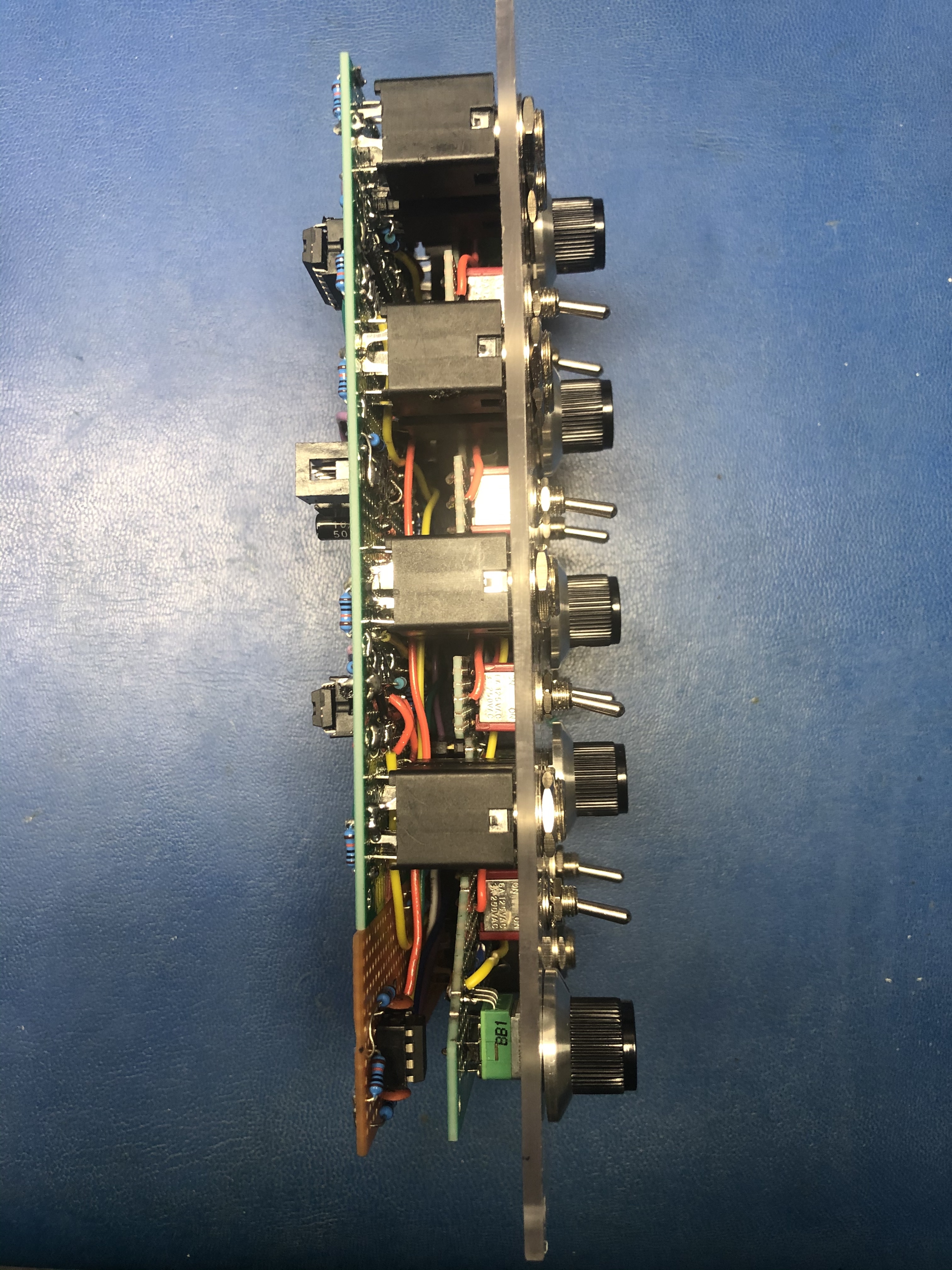
Not going to bore you all with a windy backstory so long story short: I’m building Sam’s modules on double-sided perfboards with Polycarbonate panels. Emailed Sam with some pics and he suggested I post them here.
Thanks for all of you posting here. You’ve helped me a ton on these builds - especially with the list of improvements to the VCO design. This is such a great place and an amazing community. Thank you!
Is the arduino in the 1222 backwards? Or is that for better trace routing?
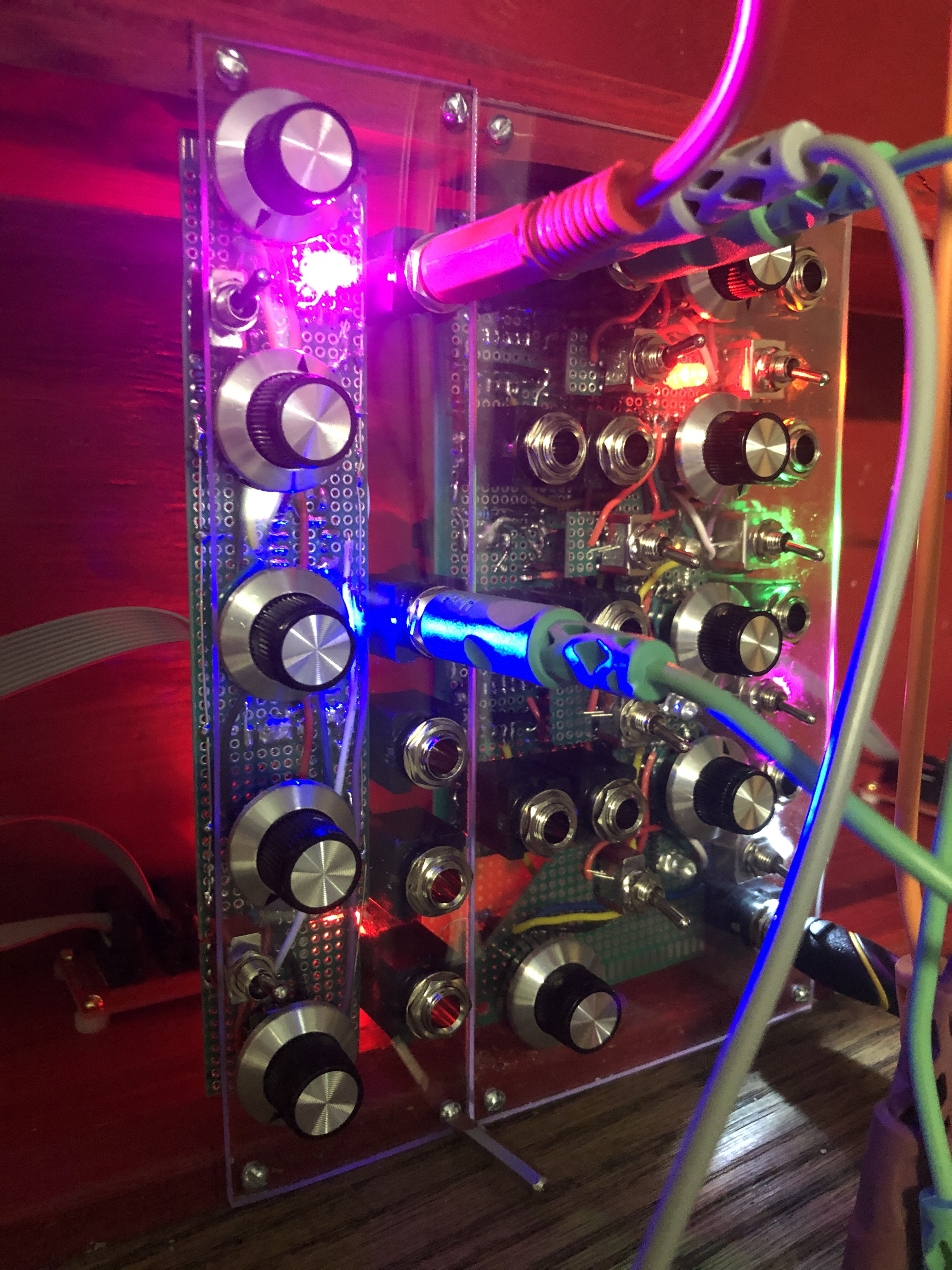
I love the look of the clear poly’. Hmm makes me wonder about edge lit blank panels.
Welcome to the forum, you will be more than at home here =P
Thanks! The Arduino was mistakenly wired backwards. I got pin 1 of the socket facing the wrong way and didn’t notice until first power up. Oops!
I had the same thought about lighting… might be cool to route a small channel on the top/bottom of the case under the panels and throw a strip in them. Create a panel for case power & a CV w/ adjustable dc offset for panel lighting.
My link above is technically for 3mm, but they Americanized it for Amazon.
You could prob go a little thinner and get away with it as long as long as you have enough panel mounted components connected to a PCB for support. 3/32” / 2mm would be prime… not sure if 1/16” would be too flimsy.
1/8” / 3mm @ 20cm tall is a bit bendy at first, but stiffens right up when reinforced with the protoboard.
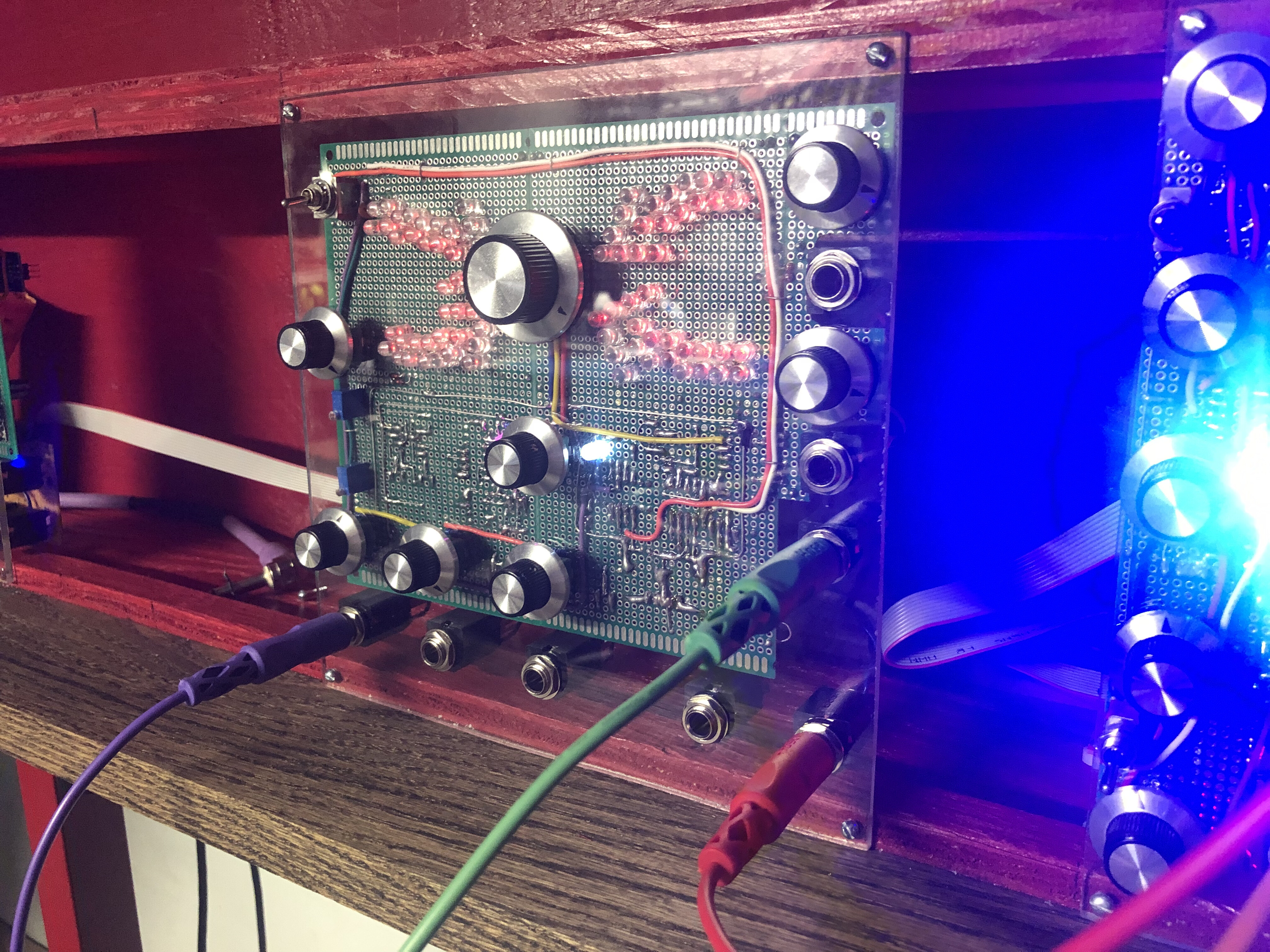
Added a circuit for the LED arrows and a white/pink noise generator based off of Electric Druid’s Noise2 chip.
The generator is fed into each the inputs if nothing is plugged into them and the white/pink noise can be selected with the knob between the white & pink LEDs.
There’s a second output next to the regular output for the noise to be used elsewhere in the synth.
I also switched out the 100ks on the inputs for 10ks and put a 10k trim pot in series to zero in on the point where the op amp gets overloaded. Works a treat and the hp/lp output match. Resonance is too low, but I couldn’t figure out how to get it higher.
Yeah, I guess not much, if I understand your schematic they’re in two groups in parallel after a transistor and 1k resistor from the +12 V rail. So roughly 10 mA for each group with each LED getting only about 0.3 mA.
That’s right and the gate of the transistor is connected to an AC signal half rectified so the LEDs are only on half the time. One set is on the positive side of the AC signal and the other is on the negative so both sides are never active at the same time. Looks really funky with a low note passing through it. Could cause seizures.