Let’s see the schematic and see if we can’t figure out how to juice that bad thing!
2 Likes


True, but my problem is this: after the 10k input swap the balance between the resonance and the signal is such that the resonance gets buried no matter what I do to rv1. I tried putting different ohm values in parallel, but couldn’t get the resonance dramatically louder.
The only way that I found to get the resonance to blend is to the turn the input1 down which also drops the output signal. I was thinking of swapping the 10k input resistors back to 100k and adding a gain stage right before the output jack, but that would reintroduce the issue with the hp and lp outputs being different.
At some point I thought the resonance gets attenuated because of the diodes’ forward voltage in the negative feedback loop, but I’m just not sure.
Any thoughts?
…I should add… removing one of the two diodes at LEDLEGS1 & 2 (I forget which one) made a massive difference. Crazy harmonics and loud. I might just remove it again and call it a day. Removing the other one had less of an effect, but still sounded cool.
The two LEDs provide non-linear feedback for the TL07x in the resonance feedback loop (once they start conducting, they’ll short the trimmer). If you get different behaviour depending on which one you remove, you may have a DC offset in the resonance loop. Check that C9 is what it’s supposed to be, and is connected the right way.
1 Like
Yeah, that’s going to limit the output to something around a diode drop. Try putting in two diodes in each branch back to back. Excuse the ASCII mess:
           ----|>|--|>|----
        ---|              |----
           ----|<|--|<|----
That might ~ double the gain of the res feedback op-amp, so give more controlled squeal rather than crazy loud harmonics.
Cheers
2 Likes
Thanks Fredrick!
From memory, there’s no DC bias, but the AC signal isn’t symmetrical with a square wave input. The overshoot on the positive side is much more relaxed than the negative side. The negative side is pretty sharp.
I’ll check it out this weekend when building the buffered multiple.
Quick question: how do you calculate what the value of a cap removing DC bias should be? I didn’t think of putting one on the output of the noise circuit until last night… don’t know what value to use. Should I put one on the output, or two - one on each output before the pot? Does it matter?
Will do! Thanks!!!
Note that the Schmitz implementation of the MS20 filter is using a (green) LED, not a diode. The original Korg design uses three diodes in each direction.
1 Like
Yeah - good point - I’f I’m reading it about right, the max gain without the diodes will be ~6.5.
Depends on what level you’ve got going in, but I suspect that the gain with two LED forward drops is going to similar. Try two LEDs, and if that’s too hot, maybe a normal signal diode plus a LED in each branch might be a good compromise.
1 Like
A decoupling cap in series with the output together with the resistance of what you connect it to forms a passive RC high pass filter, removing low frequencies — and removing DC bias is removing the lowest frequency of all, 0 Hz. So the cap times the resistance, RC, should be such that 1/(2πRC) is small compared to the lowest frequency you want to keep.
The input resistance of a synth module typically is about 100k. If we say we want to cut off at 1 Hz, for instance, then 1/(2πRC) < 1 Hz means C > 1/(6.28x10^5) F or C > 1.5 µF. Or more conveniently 1 µF will cut off at 1.6 Hz.
(A smaller capacitor will cut off at a higher frequency, but will suppress a DC level faster. It will also introduce more distortion to a square wave, which after all is in essence two DC levels for short time periods. So there are tradeoffs to consider.)
1 Like
I’ll give this a whirl… exactly what I needed to hear. Thank you!
Perfect. An analog output question answered by the man himself. Thanks so much!
Good news!
It works as it should!
@jaradical & @fredrik - I snipped out the single 1n4148s and replaced with 3 in series (your “ASCII mess” plus 1 more on each side) and it opened the resonance right up. Thanks so much!
@analogoutput - I used a 470nf on the noise output and it killed the bias. Thanks for the quick tip! I took a screenshot for future reference.
On to the buffered multiple.
Thanks again everyone!
5 Likes


Got the 2nd and 3rd 1222 VCOs done! This sounds amazing.
Front:
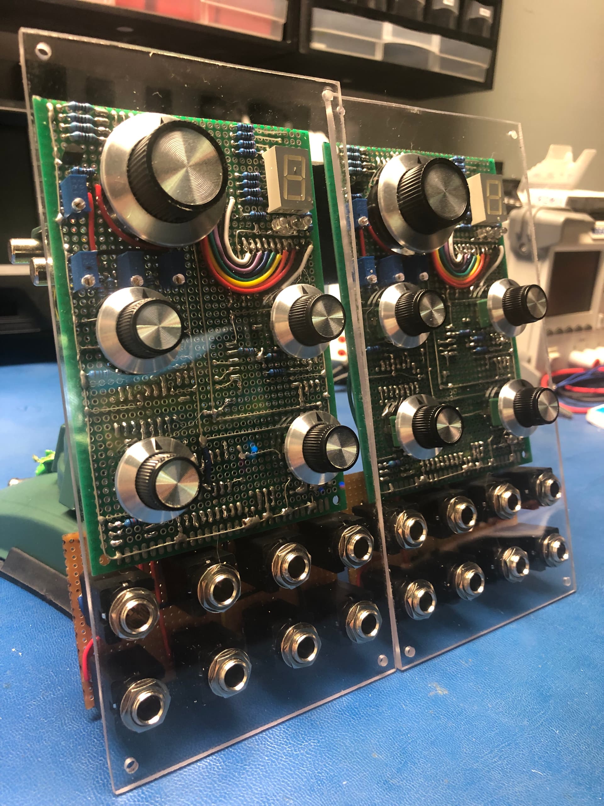
Back:

Case:

I messed around with the PWM pot resistor a bit here:

Putting a scope to the square output and maxing the pot, I noticed it wasn’t getting the full range:
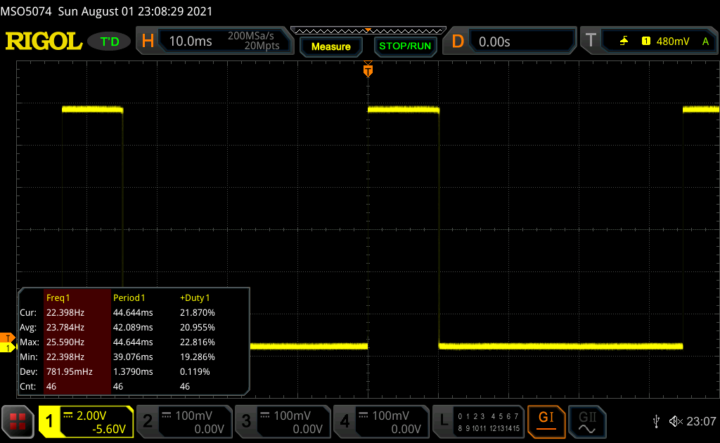
It was only about 21%. I checked the pics of the PCB to see if the board was different:

Seeing the 220k value on the PCB, I swapped out the 470k and scoped it again:

Much better! Almost 40%. I wanted the full range so after some tinkering I found 24k cut the mustard:


Leaving the rest of the resistors values gave the full 0-5V sweep the 3340 is looking for with a 10VPP signal to the PWMIN input.

The Midimuso is next (I think).
Thanks to you all. This has been an extremely rewarding project and this forum is enormously supportive.
Cheers!
6 Likes
looks great ,  the clear panels and how you can see the " guts " .
2 Likes
Much appreciated! Prob should install a mirror on the back wall of the case. 
3 Likes
Note that the voltages in the datasheet are for a +15 V supply. The PWM output is generated by comparing half the sawtooth against the PWM control voltage, and the sawtooth peak is Vcc×2/3 so if you power with +12 V the useful range is 0−4 V.
4 Likes
Ahhh, noted. Thanks @fredrik !