Reverb-O-Matic (100 FXs/Reverbs)

Inspired by a remark by Juanito Moore I made a euro rack version of a reverb unit based on a reverb board that one can buy at various places for less than 15 USD. Here is an example I found on aliexpress:

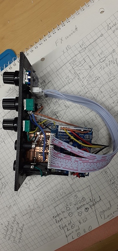
It contains some circuitry and a signal processor programmed with 100 different reverbs and/or reverb style effects. You can see it in the following picture attached to the module.

As you can see the circuit board comes with some cables. Note that the color coding of the wires may not follow standard conventions. So the red/black power cable may connect the black wire to the plus pole and the red one to minus (remedy is to reverse the connector on the pcb, or fiddle with the connector itself). I have 2 of these units, with one the polarity was reversed, the other one was as expected. Your mileage may vary!

The circuit runs on 5 Volt and is intended for use with line level signals. To adapt it to euro rack levels I added an input stage (TL071) that allows for connecting a euro rack level signal (which is attenuated), a level input which is copied, and a 2nd euro rack level input that can be used for another signal or as a feedback input. The FB pot can be used to either choose the level of the 2nd euro level input signal or when there is no jack inserted in the 2nd EIN, one of the outputs is connected (normalled) to the input circuit the pot can be used to choose its level. The dsp circuit outputs line level signals on 2 outputs (some reverbs result in a stereo signal), so I also added an output stage (TL074) that amplifies the signal to euro rack levels on 2 outputs. So the module has euro/line level inputs and euro/line level outputs. Finally I added a Dry/Wet pot.

The last picture shows that the circuitry is very simple indeed, just a few resistors and op-amps.

I found this list of effects on the net:

00~02 small hall,
03~05 medium hall,
06~08 large hall,
09 church,
10~12 small room,
13~15 medium room,
16~18 large room,
19 hal,84~85 Reverb+phase shift,
20~26 with metal acoustic reverb,
27~29 Spring reverberation,
30~35 Reverberation door,
36~39 Reverse reverb,
40~43 Early reflection,
44~47 Atmosphere effect,
48 stadium,
49 Ambient effect FX,
50~58 Delay
59 echo,
60~65 chorus,
66~69 Flange,
70~73 Phase shift,
74~79 Tone,
80-81 Reverb+chorus,
82~83 Reverb+chrome,
86~87 Reverb+tone,
88~89 Delay+reverb,
90 Delay+reverberation gate,
91 Delay+reverse reverb,
92~93 Delay+chorus,
94~95 Delay+chrome,
96~97 Delay+phase shift,
98~99 Delay+transposition

The reverbs are of reasonable quality (what do you expect for less than 15 USD !). And there is no way you can set any parameters. Juanito Moore has experimented with a VCO connected to the DSP which makes it possible to within limits sync the reverb to an external pulse. Iā€™m going to experiment with that and see how that sounds.

Iā€™ve planned to build a second one and add a schematic and some sound examples to this thread later, so stay tuned if you are interested.

Addendum 1
While I was experimenting with the DSP board I powered it from a DC supply and noticed that the board is a bit particular about the supply voltage. The chip wonā€™t process any sound unless the voltage is high enough. The 7 segment displays however will light up at lower voltages. So the fact that the 7 segment lights up is not a sign that you powered it up correctly and thus when fed with an input signal should be able to hear an output signal!

STL-files etc. can be found at the Reverb-O-Matic repository.

14 Likes

thx a lot @Jos ā€¦ nice work

3 Likes

Excellent work! Iā€™ve got one of these modules, itā€™s dead good for the price. Iā€™ve not got it cased in anything yet, been wanting to work out some wet/dry control and see if I can do some nice feedback. Just need the timeā€¦ story of my life

4 Likes

Here is the schematic I promised, drawn in KiCad, showing the configuration I ended up making.

I did not define a KiCad symbol for the FX-board but used labels to denote where it should be connected. Note, a 5 V supply is needed for the FX-board. Oh, and donā€™t forget to connect all GND-connections on the FX-board to the GND of the power supply.

Because the FX-board is originally designed for line level signals I added attenuation and amplification circuitry for adapting those to euro rack levels. I kept the line level outputs so that I can use the module in a flexible way with euro rack and line level equipment. As a result the module has one line level input and 2 euro rack level inputs and euro rack and line level outputs.

I added a feedback loop that connects the left output of the module to the input via a pot to attenuate the signal. This can be used e.g. for ever lasting reverb or if the gain of the feedback is higher than 1 for creating oscillations. This feedback loop is done via a switch in a 2nd euro rack level input jack which is closed if no jack is inserted. If a jack is inserted the feedback loop is disconnected. The input can then be used as a second euro level input.

In order to play around with reverb and feedback I actually made 2 Reverb-O-Matic modules so that I can chain them or make signal loops using both of them (feedback nr 1 into nr 2 and nr 2 into nr 1).

5 Likes

Some audio examples can be heard here:

Note, there may be some USB-interference audible caused by a ground loop in the recording setup. This is not caused by the reverb module!

4 Likes

Cool sound ! thank you again for sharing your diagram :slightly_smiling_face:

2 Likes

Changed the input stage a bit so that the line in has gain factor 1 in stead of 2.

4 Likes

Changed the gain factor for the audio output of the dsp board so that its level is closer to the dry signal level:

2 Likes

Shouldnā€™t the left end of R9 be connected to the left end of R7 to get a proper wet/dry effect ?

3 Likes

You are correct good Sir, I apparently made a mistake when copying this from my notebook to KiCad.

5 Likes

That is exactly what is supposed to happen, and it definitely works. When the pot is fully turned left or right the grounding prevents the signal from either going to the reverb board or the output. When set somewhere in between some of the signal is send to the reverb board and some to the output stage where they are mixed.

The simpler solution you suggested and withdrew has as a drawback that it can not be completely dry or completely wet. There is always some signal from the ā€˜oppositeā€™ side.

2 Likes

Not sure but i think that the att/feedback pot pin are in the wrong way on the schem : pin 1 must be GND

Thatā€™s a thing I always found funny about pots labeled ā€œAttenuationā€.
Logically, the more I turn it to the right, the more it attenuatesā€¦ which is rarely the caseā€¦

1 Like

@Dud, @eric it is entirely possible that pin 1 and 3 should be swapped. Iā€™m not very familiar with the conventions of potentiometer pin numbering. The idea is that if you turn the pot to the right (pin 2 sort of moves toward pin 1) the amount of feedback gets higher so more signal is fed into the circuit (the attenuation of the input signal gets less). But obviously you are free to implement this whichever way you want. Maybe the label ā€˜attenuationā€™ should have been ā€˜gainā€™, then the behavior of the pot would be more consistent with what you might expect.

2 Likes

Finally, during New Year holidays I finished my version of this module and it sounds pretty cool.

A clock control adds a whole new level to the effects. Note, it doesnā€™t sync to an external pulse though. Instead, you can control time parameter of the effect by speeding up or down the frequency of DSP. For example, with manual control you can match the delay time. Plugging LFO to cv input gives you all kind of weird sounds especially on tone presets.
When you lower the frequency, the output gets noisy because you are basically changing bit resolution. So you may want to change the 100k potentiometer to something smaller. Or add RC-filters right at the outputs to cut high frequency hissing.

Also, Iā€™ve noticed that people use different resistor values to match dry and wet level. Probably this has to do with the boards from different suppliers. So my advice for those who want to build it - breadboard it first!

My version is below. I probably should have added 100k resistors at the inputs and the input buffers, but good thoughts sometimes come too late :sweat_smile:

The upper input bypasses dry/wet control - I will use it for aux input from my mixer.

Happy New Year! :santa:

6 Likes

Good on you!

Ha, I see you added the change to the FX board Juanito Moore introduces in his video: to use a small part of a PT2399 as a CV controlled VCO that controls the timing circuitry of the FX-board. Well done! Iā€™ve had that on my list as an improvement as well but have not come round to implementing that.

In the mean time Iā€™ve been working on Time-Warp-O-Matic, which is more controllable than Reverb-O-Matic. I hope to write something more about that in the coming days.

4 Likes

very interested in both circiu
ts. thanks

You can read more about it here: Time-Warp-O-Matic

2 Likes

My FX module, made with @Jos 's schem + Juanito Moore PT2399 Time pot circuit + CV IN

and a test with a VCO

9 Likes

Excellent !! This one is in my project list for a moment, juanito have make a really good work with this nice cheapy module ! I didnā€™t know that the pt2399 can be use like a clock generator to control a quartz, really ingenious and usefull for some next bendings! :slight_smile:

1 Like