where did you find the juanito Moore PT2399 added cv circuits?. This fx unit turned out awesome.
1 Like

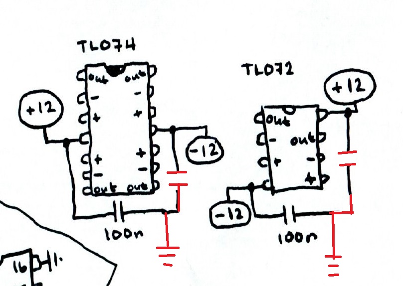
The right side here doesn’t look right:

Pins 11, 13, and 16 are opamp − inputs, and 9 is an opamp output. Grounding inputs and outputs is not how you deal with unused opamps, unless you want them to saturate, consume extra power, and possibly get damaged and take out the rest of the chip with them.
The + inputs are internally connected to a VCC/2 rail (pin 2) so seems a better approach would be to connect 9-10, 11-12, 13-14 and 15-16.
EDIT: The 100n in the upper right corner there is also wrong. Decouple to ground, folks, not between the rails.
3 Likes
thanks alot really appreciate this send out , synth on brother
1 Like
even if the PT2399 is only used as a clock source
The opamps are still opamps and will still do opamp things even if you’re not using them 
1 Like
ok thx, maybe i need to take out of my case to mod it.
just connect it by couple , and keep the GND connection like this ?
1 Like
No GND, you should connect output to input (which is the inverting input) for each pair of pins. Here’s the block diagram:

and it’s this pattern you’re after:

The non-inverting inputs are connected to VCC/2 already.
But I wouldn’t stress; this might well be an “if it works it works” case, but if the IC gets warmer than expected or burns out this could be the reason.
2 Likes
thx @fredrik , I will make the modification
to be sure, like that

because I also shared this schem on my website with the construction, and if I add this info I prefer to be sure.
and this ?
1 Like
This looks like too much fun not to try!
THANKS! 
2 Likes
Well, I haven’t tested things, so all I know is that the original is wrong ![]() – but given the block diagram the top two connections (15-16 and 13-14) are obviously correct, the other two already have the output connected to the input via a 4k7 resistor, and internal connections to MOD/DEM, so may be safer to leave them unconnected (not grounded) to protect those circuits. I have some 2399s somewhere but no time to experiment right now.
– but given the block diagram the top two connections (15-16 and 13-14) are obviously correct, the other two already have the output connected to the input via a 4k7 resistor, and internal connections to MOD/DEM, so may be safer to leave them unconnected (not grounded) to protect those circuits. I have some 2399s somewhere but no time to experiment right now.
Your decoupling update is correct.
1 Like
thanks, but now I have connected by couple as above this afternoon.Is it less good ? I hope it will be alright, in any case it still works
thanks for your diagram… but could you tell me what pin X1 means, where it should be connected??? Thanks…)
1 Like
I should have added one of these onto the end of my synth build. But now I don’t have room for a display and a pot.
for the optional part of Juanito Moore with the PT2399, the X1 must be connected to one of the 2 pads of the pcb where there is the crystal timer (which must be cut), but be careful is quite meticulous and it can be irreversible for the pcb if you heat up too much or if you put the 2 pads in contact which are really very close together.
To know which of the 2 plots controls the time, you have to test (nothing dangerous for the circuit if you test the wrong one), but one hour from his video Juanito does it, it can help

2 Likes
thank you so much! now it became clear
1 Like
Hi All,
Apologies for getting here literally 2 years later…
I’ve just bought one of these after reading through a good portion of this thread, and for some reason I am getting no noise out of the output jacks.
I’ve measured my voltage going in (about 4V) and my power lines (4.5V going in), but I am getting only around 0.05V on the output and this sound comes in the form of clicking rather than just a low reverb volume out. All my grounds are connected to the power supply ground as well.
I have not added any sort of opamp circuit on either the in or out as I wanted to ensure that the module works before going to all that effort.
The video below shows my simple testing, running a saw wave straight into the in and then the out straight into my mixer.
Any questions or suggestions are very welcome.
Thanks!
That 4V sounds pretty low. Depending on which variant of the DSP board you have (there are several), it may have chips on it that require 4.75V minimum to function.
From the post at the top:
While I was experimenting with the DSP board I powered it from a DC supply and noticed that the board is a bit particular about the supply voltage. The chip won’t process any sound unless the voltage is high enough. The 7 segment displays however will light up at lower voltages. So the fact that the 7 segment lights up is not a sign that you powered it up correctly and thus when fed with an input signal should be able to hear an output signal!
2 Likes
Another addendum might be due because of this:
In my first build I did not add any input protection (the usual resistors + diodes) nor output protection to the circuit. Mine is broken now and although I’ve not come round to finding out what exactly is wrong with the module, I suspect that it could be the input bit of the circuit that might have gotten overexcited by some high amplitude signal. So I think it is wise to include input (and output) resistors and some clamping diodes.
1 Like