I agree ![]() ! It will (eventually) be open source for the more DIY inclined friends like the ones here. That’s after I’m finished kicking myself for saving all the documentation for last.
! It will (eventually) be open source for the more DIY inclined friends like the ones here. That’s after I’m finished kicking myself for saving all the documentation for last.
thanks for the compliment ![]()
I’ve never liked typing up documentation, almost all my notes taking uses a Personal Analogue Device with a graphite interface (a ‘pad’ and pencil for short) and I use a scanning app to take regular snapshots of my whiteboards.
I once heard my uncle, a retired electrical engineer, talking to himself while repairing a broken circuit board. He sounded like he was telling an old yarn to an interviewer on a chat show.
I asked if talking to himself helped remember what he’d done (he’s 98!). He smiled and pointed to the microphone on his shirt and then to his workshop pc running a voice dictation function on Google docs! Like I said, 98 but he can still run rings round me!
I look forward to the release!
Hey it’s me, your friend
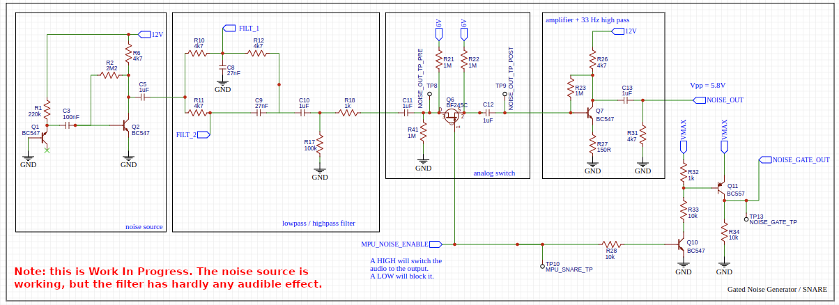
Patternate-O-Matic, the analog sequencer I made a while ago, unfortunately has a weak filter in series with a gate-able noise source and I’d like to do something about it. In the added schematic you can see the filter section in the 2nd block from the left. Note that a potentiometer meant for controlling the filter has its middle pin connected to GND and its left and right pin connected to FILT_1 and FILT_2. Switching the noise source via MPU_NOISE_ENABLE works nicely, but the effect of changing the potentiometer has no clear audible effect. I have been experimenting with some cap values, but so far to no avail. Obviously I could leave the filter out and use an external one. Nevertheless it would be nice to get this configuration to have some effect. Any tips?
Are you sure the caps and resistors are in the right place? The passive low and high pass filters should be the opposite from eachother, and I would think the combination should come out of the center pin of the pot meter.
I think this picture I found online should do the trick:
Thx. The schematic you are suggesting looks ‘sound’ to me, so I’ll give it a go and have a listen.
Sounds and looks great. I’ve build it myself a while ago and sounds great too except (here its comes).
When running a melody sequence (tri wave into the wave folder, output wavefolder into my steiner parker filter), i hear clicking. Sounds like a gate pulse but since the wavefolder has no gate input, where does the clicking come from?
When connecting the vco tri wave ditectly into the filter, the clicking is gone so the click must come from the wave folder.
I looked up this clicking thing and google AI told me that this is common because of diode switching during folding. This leads to a clicking sound at the output of the wave folder.
Can someone confirm and how to solve this? Maybe a small capacitor somewhere? Thanks in advance for your help
What exactly have you built, the topology @SynthesiS suggested? Wavefolder? There is no wave folder in my design. So you must be speaking of something else. Please explain by adding a schematic.
The one I built does not behave that way and I think it is a quite straight forward design apart maybe from allowing you to choose between 2 LED-types (used as diodes). See Fold-O-Matic. Furthermore the diodes in a wave folder get fed low voltages and relatively low frequencies (so low rise times) so I would expect them given the curving of their transfer function not to produce clicks. I’ve not heard them at least, but this may depend on the design.
Hi Jos
Its this one
Does this make any sense?
Wavefolding and Diodes:
Wavefolders use diodes to create non-linear wave shaping by folding the waveform back onto itself when it exceeds certain voltage levels. The diodes act as voltage-sensitive switches, clipping the waveform at specific voltage thresholds.
The Click Problem:
When the input signal rapidly crosses these diode thresholds, the diodes switch on or off suddenly, causing a rapid change in the circuit’s behavior. This sudden change in voltage creates a transient that sounds like a click.
Input Signal Suitability:
Wavefolders generally work best with waveforms that have a smooth transition at the clipping points. Triangular and sawtooth waves are often used because they naturally have these characteristics. Square waves, with their instantaneous transitions, can exacerbate the clicking issue.
The diodes are switching at audio rate, so I doubt that would result in any noticeable clicking rather than just some distortion. Nice try chatgpt.
Look at you assuming he doesn’t have super robot ears.
Musing on this I wonder if a failing/damaged capacitor is creating a ‘rattle’ where it’s causing a clip? Diodes can also behave oddly when their function in a circuit is dependant or overlapping another diode. Oddly enough LC, rC filters and even the simple voltage divider can affect the offset of a AC signal or add a low frequency, regular ‘clip’ like using a LFO to trigger a gate or envelope. Does it click when isolated from the case supply?
Ok , enough of my late night rambling.
All the best
Hi Farabide.
Thanks for your comment. Thats a good idea to try it outside the modular rack. I have 2x 12vdc wallwarts so should be no problem. I will try it and let you know the results.
Long time no see! This was last November already. I took the castor and Pollux github project and did order my first smd presoldered pcb! There were some issues, but in the end it does work!! And it’s a really nice oscillator!!
Hello everyone,
I developed a module to expand my 8 channel CV2MIDI - Converter in direction towards a kind of real fun “Modular Sequencer”:

It consists of 8 independent channels controlled by 8 “control cells” on the right side.
The module is pure analog with 4 PCBs hosting 2 channels each:
Anyway, this module offers a variety of new sequencer modes when used in conjunction with my 8 channel CV2MIDI Converter:
The clock behavior is controlled by cells on the right module side.
Witch each controller cell you set the clock operation for the corresponding channel / step.
Switching it to “ON” means a permanent 5V output at the clock output jack.
Switching to “CLK” means a normal clock operation.
Both are indicated with corresponding LEDs.
For working with the CVOption module a new program was developed for the CV2MIDI converter (Program 5).
This program interprets a 5V input at a clock jack as “lock”, where the sequence executed by the CV2MIDI converter changes the sequence direction, so you can define a new sequence length.
But if you define the lock as CLOCK based the sequence cursor sometimes returns at the lock position, and sometimes not. The sequence gets a randomized length.
The situation becomes really weird if you define 2 CLK locks at different positions in the sequence with different speed rates.
Then the sequence cursor is caught in different parts of the sequence at different times like a lost ping-pong ball jumping to random segments.
The Circuit
Each PCB (2 channels) has its own PSU adaptor, as the LEDs consume a lot of current.
Both front panel pots are 1k.
The CV unit (U2) operates from exactly 0V to 5V adjusted with the OFFSET and AMPLITUDE trims.
The LFO (A5) operates from 1Hz to the lower audio range.
The clock operation selection logic (Q1, Q4) is controlled by the front panel switch (J5). The clock output modes are set to 0V and 5V and provided at the output via the discrete “OR” logic of Q2 and Q3.
Offer
Spare PCBs, Gerber and LtSpice files can be obtained directly from me, just send me an email (No PM!).
At long last, here are the details of my version of the Hagiwo Euclidean Rhythms module. I mentioned this back in April in a discussion about code optimisation. Apologies that it’s taken so long to post this follow up - life sometimes just gets in the way…
I was very interested in this module but from Hagiwo’s description there were clearly some issues with the software, most particularly that the display would only update when a trigger pulse was received, and that there were stability issues if the code was expanded. Looking at the code there were several aspects which could be optimised.
With these changes made I found I could add more functionality to the module without any software instability, so this version allows saving of the current pattern settings to the Arduino EEPROM for retrieval in a subsequent session. In addition there is a potentiometer and CV input for voltage control of the randomness in random mode. The code also supports a trigger input to reset all channels to their starting step, though I ran out of panel space for the socket on my Eurorack version! In addition to the hardware SPI OLED display, other hardware changes include fully buffered trigger outputs.
So here it is -
Fuller details of the code and circuit are on my Github account for anyone who’s interested.
The naughty playground child ![]() could not keep the hands off and addad ratcheting software to the CV2MIDI <=> CVOption combo
could not keep the hands off and addad ratcheting software to the CV2MIDI <=> CVOption combo ![]()
![]()
![]()

I built the yusynth wavefolder some time ago and it works well (like all the yusynth stuff). I’ve not heard any clicking (so far). The folding effect works well on a signal that when folded will result in a different waveform than it was. I’m not sure what happens to a pure square wave.
For powering my rack modules I’m using 2x8 connectors (and flatcable) so there are 2 pins free since 6 are used for -12 V, gnd(3), +12 V and +5 V.
I’ve been experimenting with using one of the remaining pins of the powerstrip to distribute a reset signal generated from a central module (Reset-O-Matic) with a ‘big’ reset button on it.