Hi Jos.
Just found out that the clicking noise comes from my baby 8 sequencer. When i turn all the 8 potentiometers down the clicking is gone.
The clicking starts when the pots are turned up about lets say half.
Hi Jos.
Just found out that the clicking noise comes from my baby 8 sequencer. When i turn all the 8 potentiometers down the clicking is gone.
The clicking starts when the pots are turned up about lets say half.
I’m not sure what happens to a pure square wave.
With a square wave it does what you’d expect from a wavefolder - it progressively reduces the amplitude to zero and then inverts it if you continue to increase the folding beyond that point.
Neat idea!
My rack also uses non-standard ribbon cable connectors for power, though mine is 2x6 - 2x3 for ground and 2x1 each for -12V, +12V & +5. This is handy because I can use 2x6 → 2x5 cables for ‘standard’ modules that don’t need 5V and full 2x6 cables for the others. I didn’t go for the larger Eurorack standard which includes CV and gate signals, but it does mean that I don’t have any spare lines on my backplanes.
If I do eventually find that I need that reset input I’ll make a thin daughter panel for the extra socket and fill the rest of it with yet another passive mult!
To paraphrase the American songwriter Tom Lehrer, “life (and modular synths) is like a sewer, what (signal) you get out of it pretty much depends on what you put in.” ![]()
Does the sequencer have a separate ground connection?
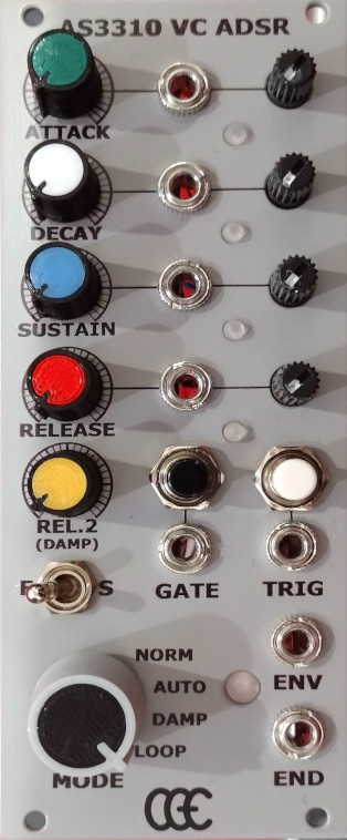
Here are some details of another of the modules I built earlier this year but didn’t have time to post about - a derivative of the Digisound 80-18 ADSR envelope generator using the AS3310 chip.
I was particularly interested in this ADSR because of its different operating modes:
The Auto and Damped modes provide exciting alternatives to a standard ADSR, but the Digisound 80-18 isn’t an ideal solution. Firstly, although it uses an intrinsically voltage controlled chip, it provides no options for control of the envelope parameters by external CVs. Secondly, it’s susceptible to repeated AD triggering with relatively weak gate inputs.
These issues were easy to fix:
This all worked well (including the auto ADR mode), but I found that the final envelope release in damped mode was too rapid leading to audible ‘clickiness’. I experimented with different resistor values between the AS3310 and the transistor responsible for terminating the envelope, but in the end decided to add a ‘Release 2’ pot on the panel to give control over this final phase of the envelope (not voltage controlled though ![]() ). I also included out-of-range monitor LEDs to give an alert if the combination of the potentiomenter settings for A, D, S & R together with any external control voltages goes above the maximum useful value.
). I also included out-of-range monitor LEDs to give an alert if the combination of the potentiomenter settings for A, D, S & R together with any external control voltages goes above the maximum useful value.
At the time I was working on this module I was also doing some remedial work on my Formanta Polivoks. One of the issues was the envelope generator associated with the filter. This has two modes (ADSR or AD) and in AD mode it should auto-repeat if the sustain level is set to zero. This latter feature (which uses an op-amp comparator to generate a new trigger pulse when the envelope output falls close to 0V) wasn’t working, but was easily fixed by tweaking one resistor value (details here). I thought this would be a fun feature to include in my ADSR and so added the required comparator, a Loop position on the mode switch, and an END output (which goes high when the envelope is complete) to trigger other events in the synth if needed.
So there it is - a multimode envelope generator with conventional ADSR, trigger-driven automatic ADR (AD if sustain is at zero) with optional looping, and damped mode ADRR². In loop mode it can be used as an LFO - the frequency goes up to 120Hz on mine. I was so pleased with the finished result that I immedately built a second one - now I just need another cabinet to put them in…
Further details are, as usual, in my Github repositories if anyone is interested.
Another from my backlog of modules - an enhanced version of the Tesseract Modular ‘Low Coast’ audio player:
It uses an extremely cheap Kebidu ‘Music Speakers’ module (I got two for about £5 from Aliexpress) which can play audio from USB, micro SD, Bluetooth, an AUX input, and has a built in FM radio. The Tesseract original just adds a dual op-amp to boost the output to Eurorack levels; I spared no expense and used a TL074 instead of a TL072 to give a mono mix output too. I also wanted to experiment using FETs to allow external triggers to operate the transport controls (previous, play/pause & next). Simply soldering a 2N7000 source and drain across each of the three switches and connecting the gate to a simple passive network does indeed allow the transport controls to switch on the rising edge of an input pulse.
I’m not sure how useful this module will be but it was a fun little project and I’m pleased by how easy it was to add the extra control options. Details are on GitHub as usual.
Great! I’ve build my second one but unfortunately no audio output. Need to investigate
Hi Jos.
I’ve build a second one (yusynth wavefolder) but i have an issue with the output. I hear the wavefolder working but at a very very very low output. When i touch pin 2 (inv. input) of the output opamp with a metal philips screwdriver, the sound is back to normal volume but only for a short time. I checked if i forgot to ground something but everything that needs ground is grounded. I used a 56k resistor as output resistor and i used a 2 pin female header pin to experiment with different values. I also swapped out the opamp. What else could be wrong?
I’ve been working on my VC ADSR for months… today I can finally stop tweaking the circuit and resume working on the PCB design. Here’s a little demo still on the breadboard.

The starting point for me was the excellent MFOS ADSR circuit by Ray Wilson, which I then massively expanded with voltage control for all parameters, LEDs, loop mode, sustain gate output, inverted output, and an auxiliary “Release only” output, which is basically an extra simpler envelope with minimum attack and maximum sustain, but same Release time as the main envelope (similar to the Release mode of the Moog Grandmother VCA). And of course, the final module will be dual ;).
Adding voltage control was quite a journey, but adding a robust loop mode that cycles through attack, decay and release was even more so, as I had to expand the logic of the original MFOS circuit’s state machine.
As always, I want one … (Maybe two)
The module will be a 15cm two-in-one, but I won’t judge you for wanting 4 envelopes (plus 4 auxiliar “release only” for each) ![]()
If you’ve done all the usual physical checking for dry joints and solder bridges, then it could be anything from the input VCA (and the associated control circuitry for the VCA) through all the remaining op-amp stages. Do you have an oscilloscope? If so, and with a working wavefolder for comparison, you should be able to work through the signal path to find where the signal levels change suddenly. I’d start by checking the signal level at the output of U2a (Yusynth numbering) which should tell you if the VCA stage is working.
If you don’t have a ‘scope then I’d strongly recommend getting one - even a very cheap one like the DSO138 mini is enormously helpful for debugging the audio frequency signals in a synth (and with a bit of cunning can be built into a Eurorack size module).
Yes thanks. I have a oscilloscope. An analog one. Old Hameg. Yeah pin 1 of U2A needs checking. For my convenience, i soldered a female header pin connected to pin 1 for easy scope readings. When i get home i will start testing. ![]()
Found it!!!![]()
![]()
Although i work very precise and cleaning after each component, i made a mistake with the 6k8 (R27) resistor between U1a and U1d. I connected both ends to each opamps pin 2 (inverted input) duh! Yeah that make sense there was no audio. Anyways it work now like a charm after following the calibration steps. Thanks all for the help.
Some pics
Glad to hear you got it working!
Thanks. Im glad too. I used my MFOS state variable filter as sine oscillator. It has a great sinewave when in self-oscillation mode. Then i used the cutoff as frequency changer to get 1khz (my multimeter has Hz to measure frequencies), and then started trimming. Yay!!
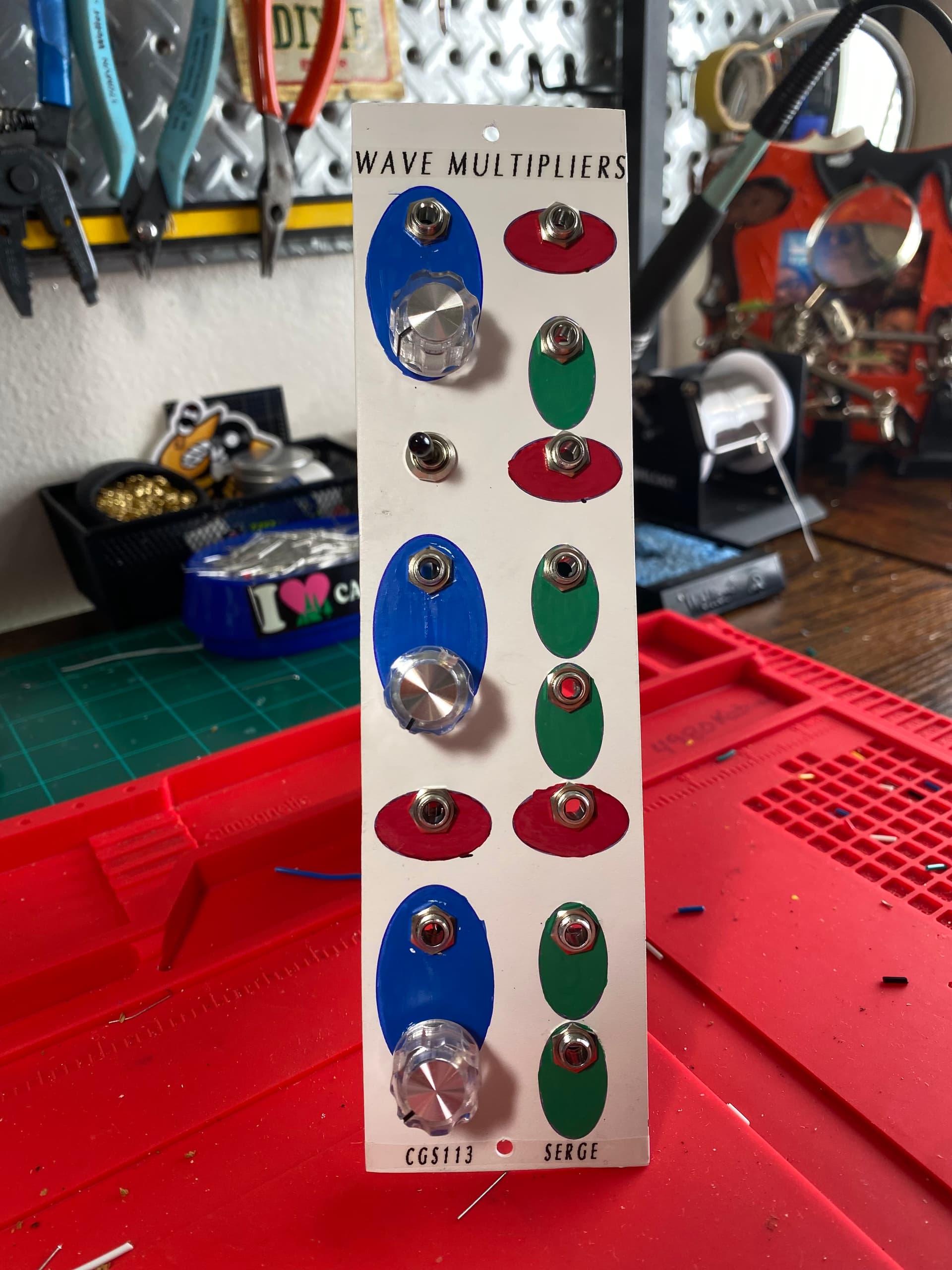
I have an update about my panel building process. I’d like to share this info, maybe it’ll help someone.
After some time I had problems with the waterslide decals. They peeled off the aluminium surface in a few spots. So I looked for alternatives and for a few minutes I was really fond of the idea of buying a UV-Printer. But then I googled a bit and to my surprise found a company in Bavaria that prints all kinds of signs and panels really cheap. The minimum lot size is 1 and the minimum size for a 2 mm aluminium composite panel is 10 x 20 cm. What a perfect size for a Kosmo panel! ![]()
I thought a good test would be to “upgrade” some well-known Eurorack PCBs to Kosmo format.
In the last few days, I received 2 packages: 1 from Finland and 1 from Bavaria:
I chose the white surface because it was the only one with 2 mm thickness. The brushed aluminium is 3mm, and that might be too thick.
Super classy. Nice work.
I’ve simulated both circuits in falstad and both work in principle.