That is a fine lookin’ print!
1 Like

A spring module. Just mechanic springs on a aluminium plate with piezo disc as contact microphone taped in the back. Makes funny noises. I’m planning on making a bigger wooden box with lots of springs and stuff and multiple piezo microphones. Maybe with a small speaker pointing inside to use it as a weird reverb box. Or even just have a feedback loop. Let’s see.
13 Likes
Sweet. Reminds me of the “pipe bomb microphone” - capped brass tube with a mic capsule at one end and a tiny speaker at the other
1 Like
Nice I love these things. Did you add an internal amp circuit or do you boost somewhere else?
1 Like
That’s just a passive thing. Those cheap piezo disks easily give out line level voltages, I tested this with a distortion module that also could be used to boost those to modular level, but the distortion itself is nice to have as contact microphones tend to be very transient heavy, so compression from distortion helps out.
Their output impedance is usually many mega ohms and input of that distortion is just 100 k, so with proper buffering they could actually output modular level voltages without any additional gain.
I just taped the piezo disk there with tape under it to tame some of the harshest transient. Glueing it would probably also make the signal level higher, but I’ll probably try different methods. Those piezo disks cost about 0,5€, so that’s cheap prototyping anyway.
1 Like
The piezo amplitude range tends to be pretty huge. It behaves like a capacitor so going into a resistive amplifier the output signal size is very frequency dependent.
The design philosophy of the amp I used was to use capacitive feedback matching the piezo in the amp, to make the frequency response more uniform, and to amplify the low amplitude stuff and then soft clip the biggest stuff.
2 Likes
I’ve built this piezo fet amp and found it to be quite good, particularly with large piezo disks. Piezo contact microphone hi-Z amplifier using a FET – Richard Mudhar
I used a fet from an electret mic capsule, I think I had to change R3 to get the correct supply voltage for my pillaged fet. Might not be the cheapest way to get a fet unless you scrounge some mics from discarded electronics… (Random thought: Nokia cordless phones have nice looking electret mics in them, I have one waiting for testing)
1 Like
I hate sound of piezo pickups on acoustic guitars on live performances with passion. They sound so horrible always, I’d rather listen to clean electric guitar than that sound of someone beating a metal bucket. They may work when guitar is played with finger picking and softly, but mediocre rock guitarist bashing acoustic guitar like it owns him money is just bad. This may or may not be related to the preamp designs and general mis-use of equipment guitarists usually perform.
2 Likes
The springs are a nice idea.
Here’s my piezo circuit: Clockwork Controlled Oscillator, with clamping diodes to tame high-voltage transients.


A little Arduino Nano experimentation board I’ve put together, using a protoboard repurposed from my CMOS synth project.
Almost nothing is hardwired, pin headers + dupont wires let me configure inputs and outputs.
I used a bit of modeling clay to support the pots that protrude from the board, and printed a tray the proper size, and adhesive putty behind the board.
Should be much more reliable than breadboards or circuit simulators to test behavior while at the computer! Currently, I am kinda working on a multi-stage envelope idea (think Alpha Juno + bells + whistles).
6 Likes
I built a version of Mutable Instruments’s Braids. I bought the PCB’s from Modular In a Week’s Kristian B.

It is powered by a Blue Pill and contains no SMD components.
To the right of it you can see the ‘beaks’. It is a thru hole clone of Mutable Instruments’ “peaks” and is also powered by a Blue Pill.
Next to that is ‘Switch-O-Matic’, a dual analog switch I designed around a CD4066 and built last month and finally Valve-O-Matic, my rendition of the Valve-caster.
8 Likes
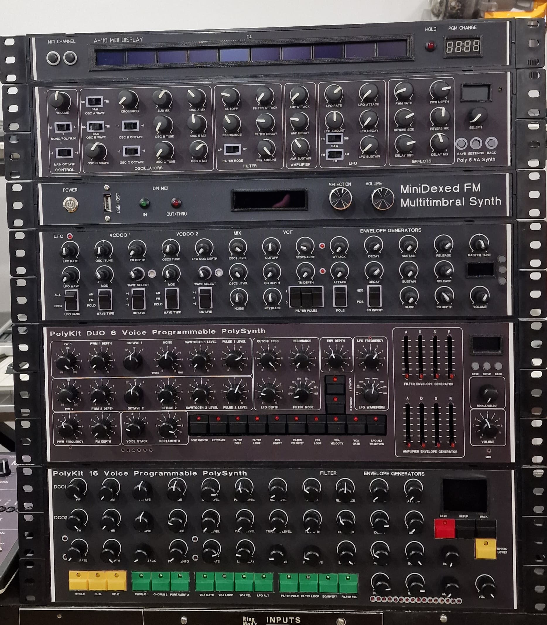
Very cool. I’ve seen the midi display before but didn’t realise it was your design. Also, how does the volume knob work on the MiniDexed?
Thanks, volume knob is just in series with the outputs, it’s a stereo 100k pot.
2 Likes
Testing the Noise Bells from @analogoutput (based on a hackaday circuit).
Really cool and simple percussion stuff!

5 Likes
Three @moritzklein designs on perfboard, thank you Moritz:
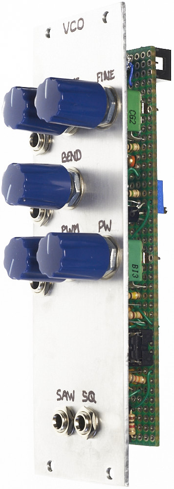
VCO, 8HP
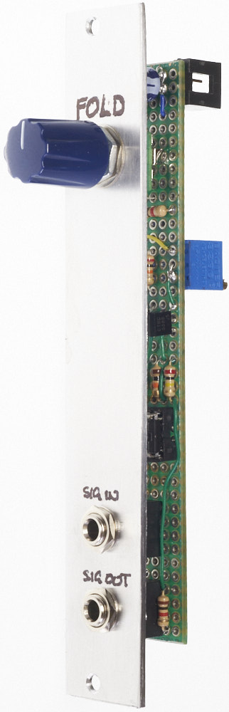
WAVEFOLDER, 4HP, without Moritz’s saw-to-triangle circuit

VCA, 4HP, centre-detented attenuvertor CV control
13 Likes
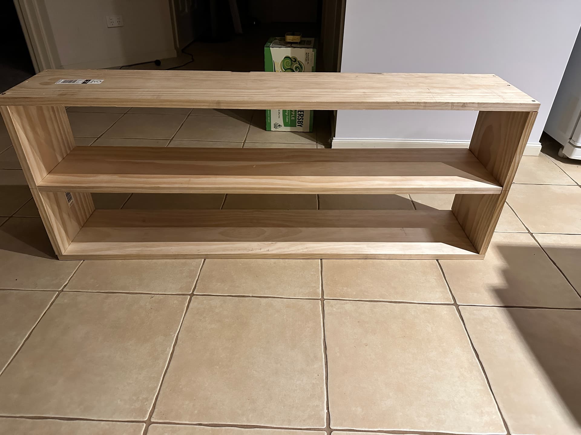
Today I started building a new rack for the Kosmo gear. It isn’t finished yet but is getting there. I am NOT a good carpenter. ![]()
9 Likes
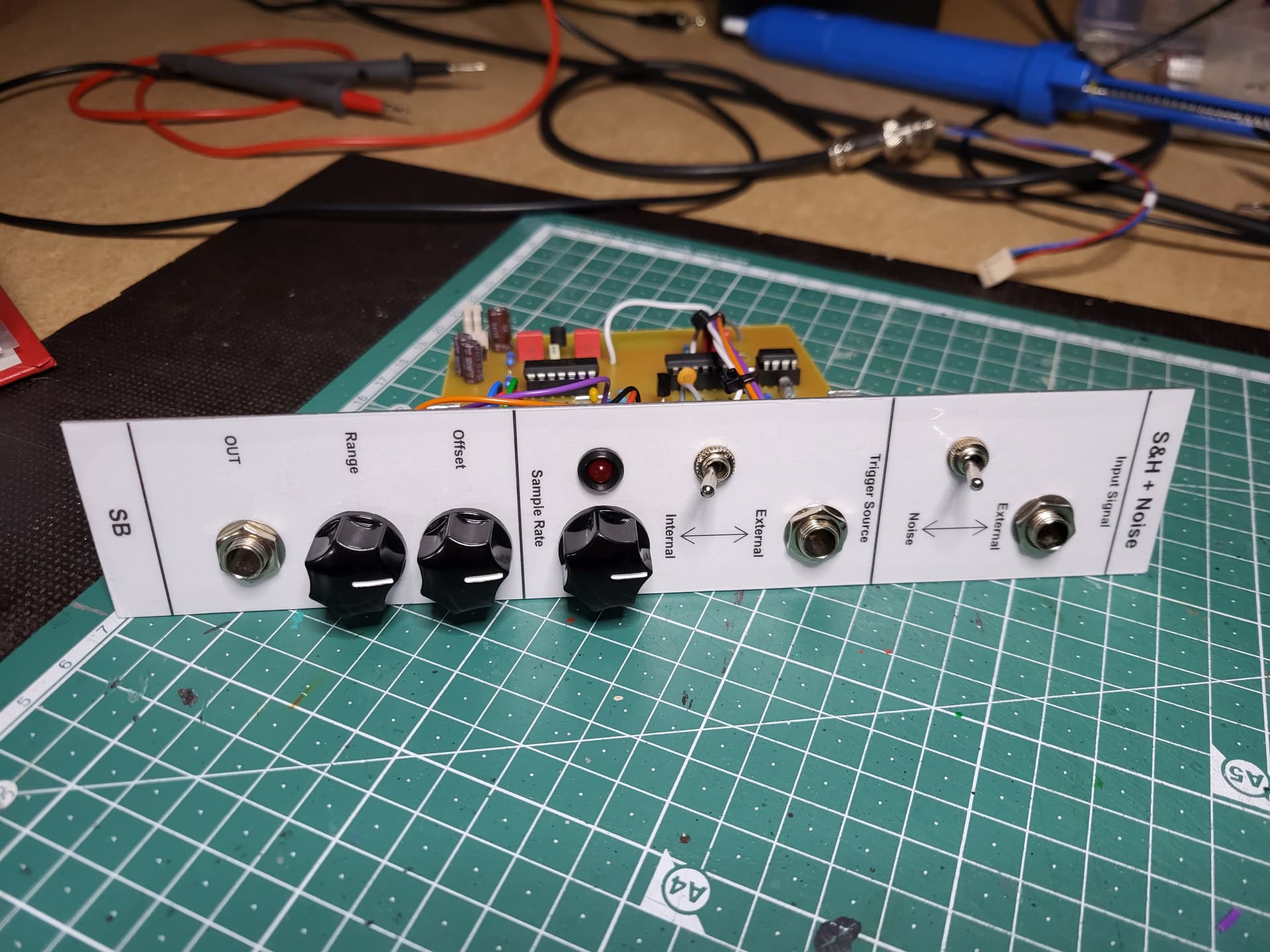
Here is the final result of the current module, a combined noise and LF398 based sample&hold.
The schematic is a mixture of @EddyBergman Sample&Hold (Eddy Bergman.com: Synthesizer Build part-51: SAMPLE & HOLD new version., based on Renè Schmitz’ work) and the noise source from @Dud (White Noise + Sample & Hold module).
Even its a very simple module it took me quiet a long time due to some mistakes… PCB no. 1 was completely wrong (I designed it under the influence of Novaminsulfon after one week in hospital ![]() - no good idea). PCB no. 2 worked quite well, but I made some mistakes in connecting the pots and some resistors.
- no good idea). PCB no. 2 worked quite well, but I made some mistakes in connecting the pots and some resistors.
But now its working fine.
for more information please have a look at GitHub - stephanbuergel/Sample-Hold-with-Noise


11 Likes
Nice. I encourage you to add a comment IN the schematic that it is tested / working so that when search engines find it the status of the schematic is also know when shown out of context. Often times it is not and people can end up building something that is not guaranteed to work.
4 Likes