HAGIWO Oled CV/Gate sequencer (mostly) complete! I still need to sort out a little issue with the diode protection circuit but it works.
Plans:

HAGIWO Oled CV/Gate sequencer (mostly) complete! I still need to sort out a little issue with the diode protection circuit but it works.
Plans:
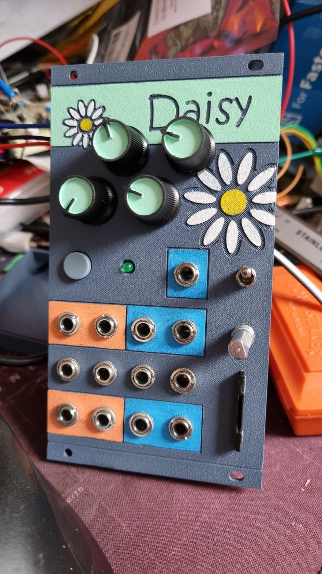
Currently working on this (basically an Electrosmith Daisy patch.init() clone with an added rotary encoder).
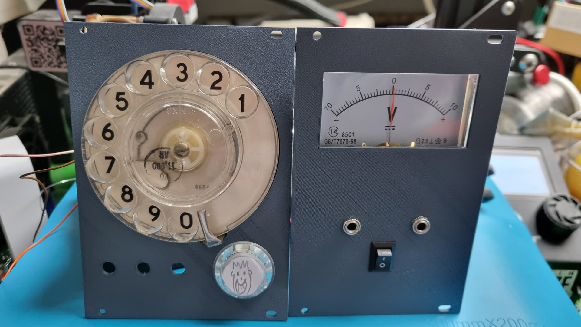
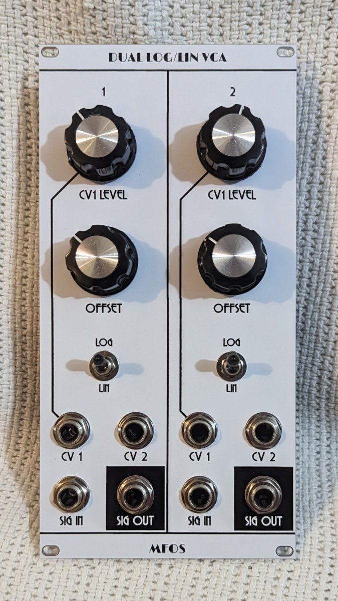
Also got these made (photo taken before finishing the dial module).
Voltmeter is just a voltmeter with passive multiples to get in and out. The switch turns on the illumination of the dial.
A little MCU learning project I’ve designed and built today!

It’s a gate sequencer based on an Arduino Nano.
Yeah I could just have used a 4017 but I’ve built a lot of CMOS stuff and wanted to learn more about designing for MCU. And I gave it a few interesting features taking advantage of its digital nature:
Is there, like, interest in me documenting it? Bear in mind it’s just a learning project and the input section is poorly designed (but it works).
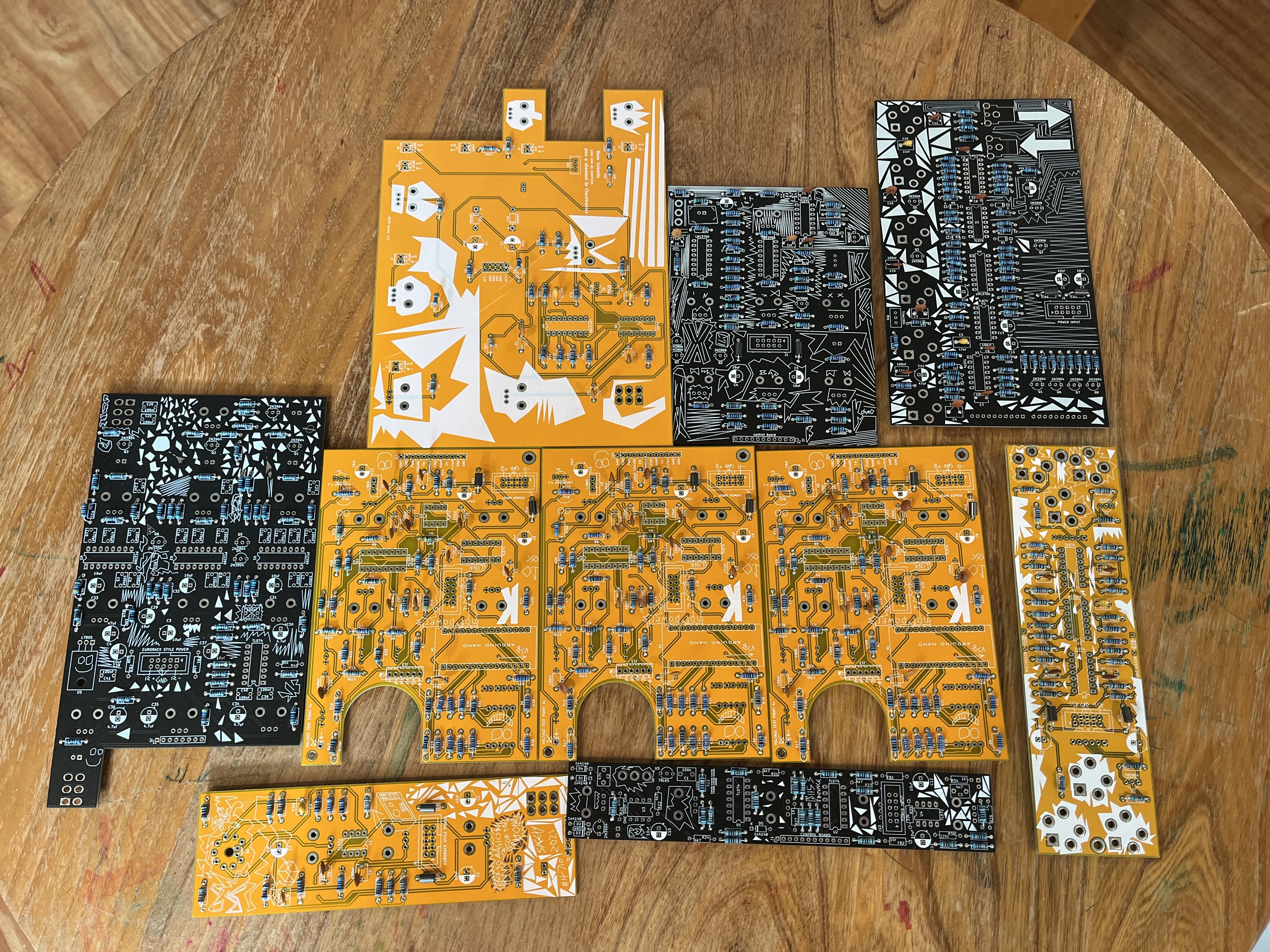
Probably not recommended, but given a little one that needs my attention in the evening I’ve been working in parallel, not in series. Believe I’ve got components in 17 different boards, but I think I’m at 90% on 10 different modules:
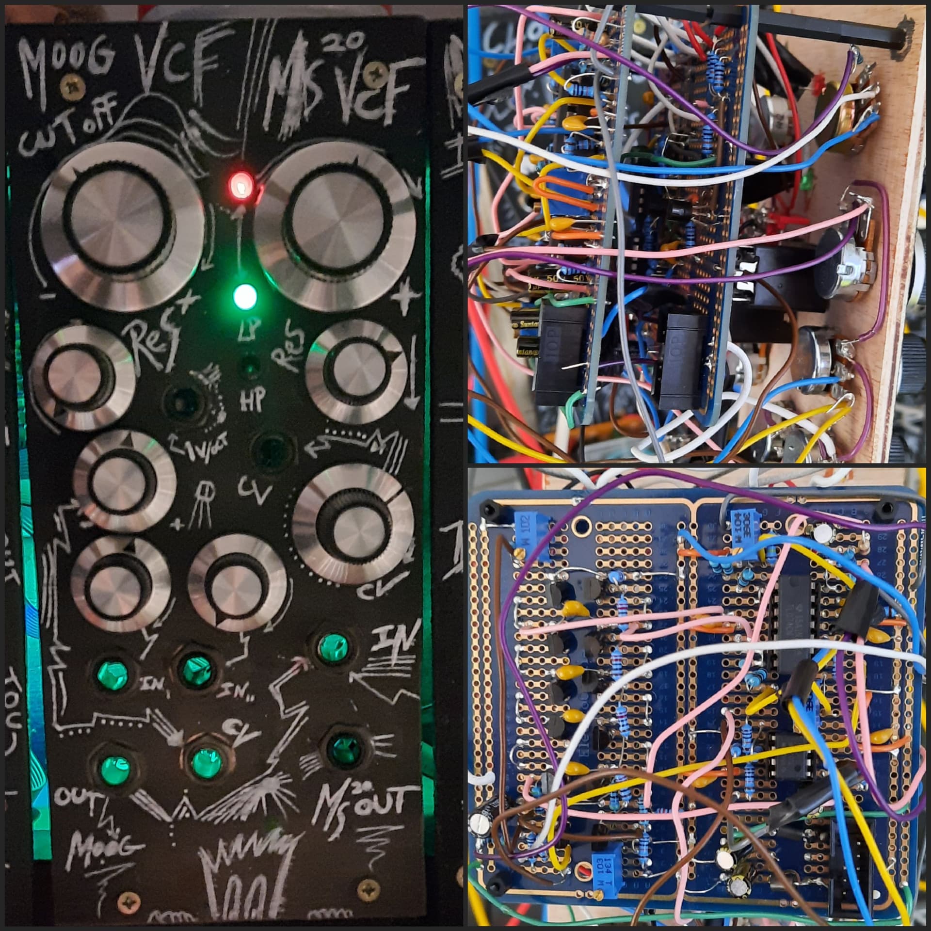
I finally decides to make a moog type ladder filter. After making the diode ladder one, I realised that I found my MS20 vcf a bit flat. So here it is. (Kassutronics version)
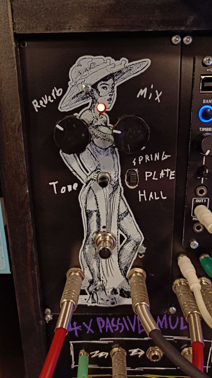
More weird conversions. TC Electronics Skysurfer (which lends its look from Strymon Bluesky) to Kosmo. It is actually a horrible reverb pedal. Instead of reverb it adds some kind of lo-fi mush, three different modes of it even. I didn’t find any use for it with guitar, but it costs 45 € new, so selling for 20 € would be pushing it, but maybe it has more use with my lo-fi synths. The mix goes to 100% wet and it has handy bypass-switch.
I just removed the circuit board, drilled holes for controls and couple of extra for those stands which were part of the aluminum case. And I removed couple of thick plastic washers from the switch mechanism to make it need less force, that worked out fine.
There’s first resistor divider to get signal level to one tenth, then half of TL072 as a buffer with wire soldered to pedal in, and from pedal out a wire to other TL072 with 10x gain and to output. Then there is 9 volt regulator for power. This seems to be a digital pedal and I don’t have schematics, so I didn’t want to risk it and test if it would work with 12 volts.
Also, because of the guitar pedal shenanigans, the input jack has to have a dummy plug to get the power going. I could have just soldered couple of places together, but this seemed easier.
And I managed to lose the tone knob already, it should have the same as the other two pots have. And hole for the “reverb”-type switch is horrible.
The hunt is over. I had to build a separate case for the toys. My best Case so far 2x77cm and 20cm deep. with extendable beer holders hidden in the base. the paint is stil wet in some areas…
I like the cheat sheet!
Maybe that would have been different if you had stacked its PCBs like you did with the ladder filter ,
really need to build these types of modules I like yours well done and classy great job
Very Nice !
…
.
.
.
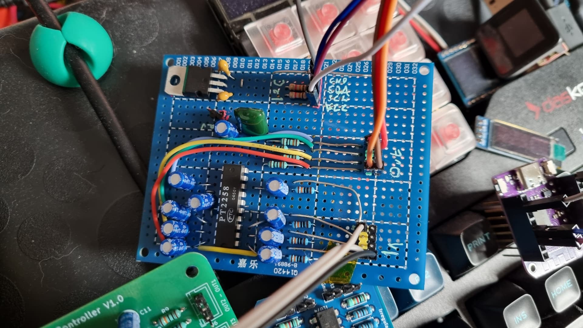
I’ve been playing with PT2257 and PT2258 chips. The best way of describing them is as digitally controlled attenuators I think. You control them over I²C and each channel can be attenuated from 0 to -79dB (in whole dB steps), plus total channel muting. The PT2257 is an 8 pin chip that can do 2 channels, the PT2258 is a 20 pin chip for six channels.
I started off with the PT2257 on a breadboard to get an idea of what could be done, then moved to a PT2258 on a protoboard:
I only hooked up four channels because my intended use case didn’t call for any more, but it worked really well (despite the horrors of the protoboard) so I decided to commit to a PCB - and found a perfectly serviceable one already available on PCBWay, so I ordered some. (From JLCPCB.)
I really like them ![]() I can’t remember why I picked them up, it was years ago (well before Covid messed up mind, memory and the concept of time) but I’m glad I did. I think I might have had an idea to combine an envelope generator and VCA in one, or a weird programable mixer, so I’ll try those sometime.
I can’t remember why I picked them up, it was years ago (well before Covid messed up mind, memory and the concept of time) but I’m glad I did. I think I might have had an idea to combine an envelope generator and VCA in one, or a weird programable mixer, so I’ll try those sometime.
Did you ever end up making your own power supply?
Yes I did! Though I still haven’t installed them, I should get to that…
I managed to finish the MIDI Ultimate in time for our annual DIY meeting in Gothenburg and as I was supposed to talk a little about synthesizers to the group (this was actually a DIY HIFI meeting), I could use the Ultimate to show how some sounds could be made (but also played very MOOGY music).
Now the Ultimate is waiting for finishing touches and I is working on my modular thing. Finishing a lot of panel wiring (stumble on some poor documentation ![]() ) and worst of all - some of the 3.5mm sockets are WRONG WRONG WRONG. They sort of is “too deep” so the male connector don’t latch. See pic below. besides some connectors are absolutely impossible to solder
) and worst of all - some of the 3.5mm sockets are WRONG WRONG WRONG. They sort of is “too deep” so the male connector don’t latch. See pic below. besides some connectors are absolutely impossible to solder ![]() .
.
Also managed to fry a pair of voltage regulators (78/79L15) and possibly a TL074. Lesson learned - Double check the orientation of ICs. I will miss that when I do something fantastic with an M110 …
Else, I am doing fine - a simple 10W tube amp I managed to start working, stopped working and is now working again. Maybe the change to a BLUE pilot light made the trick.
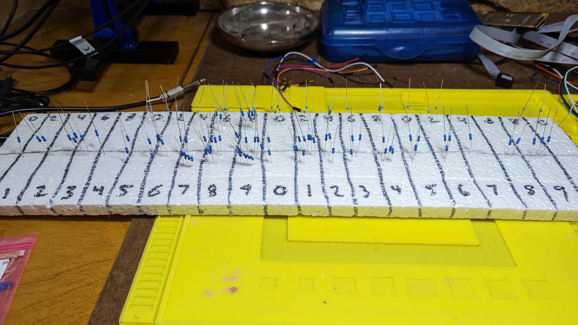
I have spent about 5hrs over the last week sifting through all the resistors that were not in their storage boxes… Being colourblind I had to meter every one to find it’s value to put back where it should be. must have been 100+ . A colleague just sugested bin the lot and buy again!!
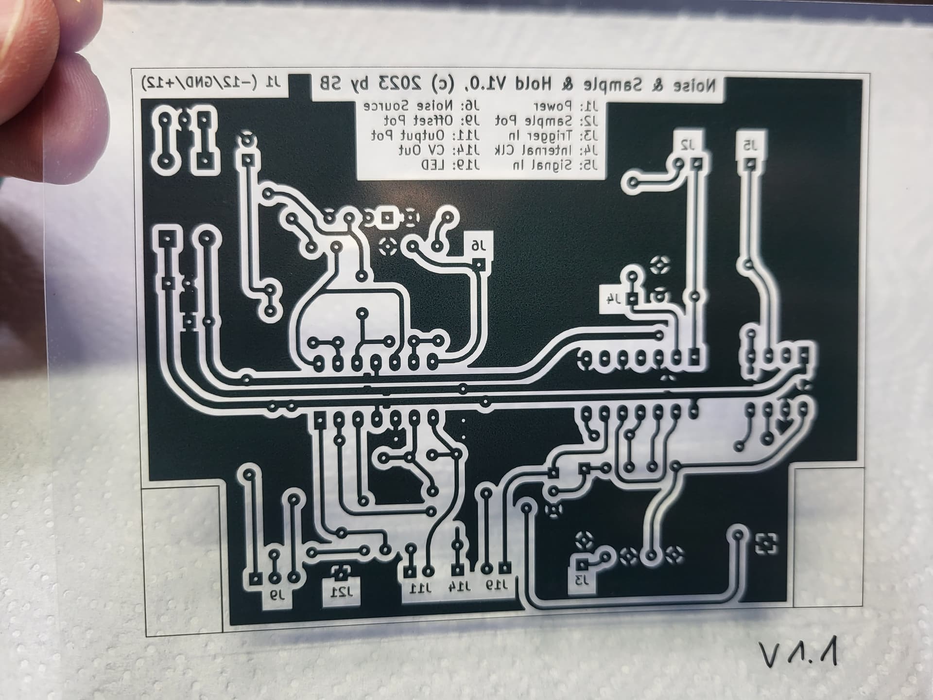
I made a quantum leap in the quality of my DIY pcb production ![]()
A bad toner catridge (no name! - the first and last try of such cheaps toners) for my Brother laser printer and the lack of transparency paper forced me to change my diy pcb creation process. I bought a pack of transparent overhead slides compatible with my inkjet printer. The rest of the process is unchanged (160s exposing with my UV light source and etching with Fe(3)Cl - the result is dramatically better than the old one. Perfect sharp details, no holes in the traces, and I am now able to increase the distance between components and traces.