Did you check on the floor?
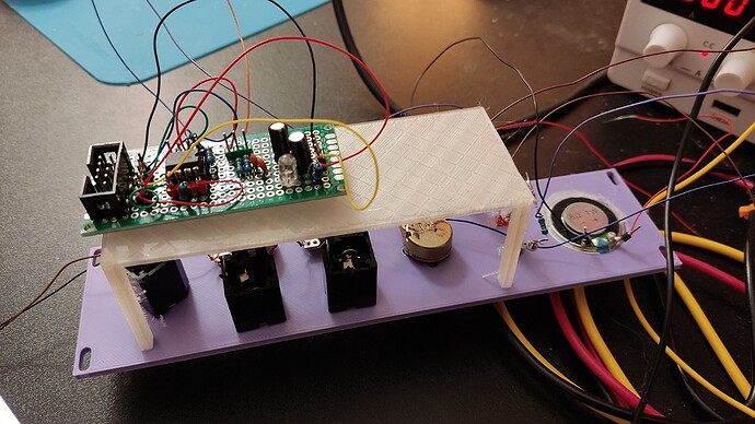
Some more troubleshooting needed, and some design modifications. I haven’t actually gotten it to display a trace yet, but I’ve made some progress since the first attempt to turn it on. And no, the final front panel — assuming the project gets that far — will not be a janky 3d printed orange monstrosity.
We just passed post 5602 here.
That number brings up memories!
Ever programmed one?
The Commodore 64 had one with a built in PIO (which was called 6510). One of the programs I wrote for it in assembly (in 1986 or so) was a preemptive multi tasking kernel, so I could run 2 basic programs ‘at the same time’.
When I showed this to my brother (who did not know anything about computers), his reply was: “Oh, is that normally not possible then (running 2 programs at the same time)?”.
As the saying goes: “Don’t cast pearls before swine …”
6502 do you mean, no 5602
Ha, ha. Indeed! 6502 not 5602
come back in 900ish posts ![]()
We have been discussing old MOS,Moto,zilog Processors a lot recently on our weekly “Covid Virtual Pub” nights… Bit of a coincidence ![]()
I got pcb’s for that. Midi jack has wrong footprint and I forgot to sync the pins on the connector on the jack board to the main board, so jacks on basically randomized. But nothing blew up and I can finish the code with this and If I want to add something… well, I have to order new pcb’s anyway.
scored this 7 foot aluminum telecom rack at re-pc a couple weeks ago, I cut it in half and finally got around to installing it ![]()
looks interesting, 1st PCB?
I think we have a very long list of ahhhhhh NEXT, PCB orders…
Fist time I see a case in a flower bed, nice !
With these type nylon standoffs (my fave) I usually fit to .1mm tolerances with a little sandpaper. Gets my stuff aligned just right. Just have to notate how much to remove for the next build.
Very cool… an O-scope! I can put my old Tektroniks spare back on the bench soon!
My build progress is here ![]()
Every (shelve in a) rack deserves at least one scope.
I agree. Would really like to make one. Sigh, the list only gets longer, never shorter
With a beefier regulator, and with some really shameful soldering, or lack thereof, corrected, progress has been made.
Not finished any new things since I last posted, but it has not prevented me from starting new things.
That one will be CMOS bells. Having a bit of trouble with the circuit but I’m confident I’ll get it to work. I’ve started to add wire wrapping to my arsenal of techniques — using also breadboard PCBs and pin headers, that makes it easy to debug things with dupont wires first, then commit using wire wrap.
The center module has a little speaker and a two channel mixer, but I still need an amplifier chip to finish it. Hoping to get a clipping indicator circuit working too.
And I’ve even branched into building acoustic instruments:
Also, I’ve just sent this to JLC — let’s hope the reviewer will humor this:
It fits in 100×96mm, below the maximum to get a special deal. When you use it as-is, you just need to populate one set of power components (shrouded header, diodes, capacitors) — but you could also score the board in the center and cut it in half. A notable feature here is that the two power rails are reversed, and there are ground pads in the center: that means that you can often use solder bridges where you would need a wire otherwise. At least in theory… I’ll see how well it works out in reality.
Just finished the VDCO from electroDruid, following the manual from the website and the very good advices from @EddyBergman website. (I am taking a long break from my DFAM clone / LMND)
It is a bit noisy, nothing that would stop me from using. It wasnt as bad while i was tuning it but then the 2 boards were further apart. But now that they are stacked together it is audible… but i have also added a mixer (for the osc and sub osc) with distortion so actually, more noise is best🤘.
Planning on finally doing the triple splashback, along with a dual lfo, VCA and Env Generator to fill the updated case.
Have you done all the mods to the VCDO to improve the noise?


