Finished soldering my Kosmo boards. Now I just need to know how to use it.

Next up is the midi interface
Finished soldering my Kosmo boards. Now I just need to know how to use it.
Next up is the midi interface
Would you consider sharing a description and schematic of this device? I have a few of those 8x8 led blocks and I’m looking for a use case for them …
I can’t post PDFs, so here’s a Dropbox link to the PDF: Dropbox - step-schematic-rev1.1-012823.pdf - Simplify your life
And here’s an image of the same:
Trigger outputs are sent directly from nano’s digital outputs, so nothing fancy there. The shift register is only involved in updating the LEDs.
In the current implementation, one row is briefly displayed at a time, by first setting the nano’s LED_ROW_x pin HIGH, then sending data to the shift register, where an output driven low will turn the LED on, and an output driven high will keep the LED off. The rows are updated in sequence just slightly faster than the visual “flicker threshold”
It’s an few months old design from this:

So in the time since, I learned more about shift registers and will probably rewrite the code from scratch (again) but at the moment it uses this library to handle shift register stuff. To be honest, though, after watching this video, shift registers are so painfully simple that it just seems silly to be using a library to control them. For a while I did think they were ALiEn MaGiCk TeChNoLoGY
To address your situation specifically, I think you could either add a shift register to handle the trigger outputs, or a second register to control the LED rows, either way, I think to get 8x8 you’ll need another one.
EDIT: 1/28/23 updated image and link to schematic after revising output protection diodes, thanks to @antoine.pasde2 for the suggestion
Your diode setup on the trigger outputs is a bit strange, once an output is set high, there is no way to pull it back low.
If you want to protect the nano’s outputs from a short to a supply rail, you should put the schottky diodes on the other side of the resistor and have them connected to both rails.
Like in this post, replacing “analog input” by “digital output”
The way the diodes are setup now, if the power supply is capable of supplying a short circuit current of more than 1A, a short to the -12V rail will first blow the diode connected to GND and then apply about -11.7V through the 1K resistor to the nano’s pin which it might survive, but the diodes will have made no difference.
Thank you for pointing this out! I think you are right, I tried shorting an output to the -12v rail and the GND diode quietly fried, but the nano survived! Trigger outputs work as expected after the short. I tested this with a 1A wall wart, other supplies might yield a more spectacular failure. Either way, those poor diodes should have some current limiting!

I changed the outputs to look like this:
Note the ATMega has internal protection diodes. However, they’re rated for a maximum of 10 mA current. 11.7 V across 1k is 11.7 mA, so is pushing your luck. I’d expect 10 mA is conservative and you could realistically go well above that, but I wouldn’t count on it. On the other hand, external 1n5817 diodes are rated for 1 A forward current.
Where the heck do you get Nanos cheap enough for destructive testing!? ![]()
From here:
I only get 168P, and use it for very simple things. For example I compiled most of HAGIWO nano designs on a 168P just fine, the only ones that had trouble were the Mozzi-based ones
$2 isn’t bad to “know what happens when…”
at least then it’s a choice, instead of a tragic surprise later on, when trying to make music ![]()
Huh, prices have come down since I last looked. Even the 328P are only $2.51.
They have started charging more for shipping though, so you have to chose your vendor wisely.
I’ve never spent so much time breadboarding a circuit as this one. I started on it weeks ago. I’ve filled page after page with numbers I then put into spreadsheets and calculated things and graphed them. I added trimmers and swapped component values and tried out different sub-circuits. Finally I said “good enough” put it aside. A day or so later I said “not good enough” and got it out again.
Now I think it’s good enough. I never actually did breadboard the entire thing but the part I didn’t do is the how-can-it-possibly-not-work part. No really.
I’ve had a couple builds on hold while I was doing that, I’ll finish them off and then I’ll get the PCBs made for this one.
And then we’ll see if it all paid off…
It doesn’t look that complicated, because it isn’t. But it needs to be tuned right for it to work well.
A way out or a way (back) in: IO-O-Matic.
I needed some “converters” so that I can connect the 3.5 mm rack components to my 6.5 mm jack mixer and vice versa.
Well, it’s not behaving entirely correctly but it’s not emitting smoke either. Enough for tonight, I’ll do my usual procrastination on troubleshooting.
Here’s some progress I’ve made. not going as fast as I would like but with a job, a household and a toddler that just had his first birthday this weekend I guess I can’t complain.
Wood for the case finally arrived (2 weeks late)
Meanwhile started soldering the PSU and first VCO. unfortunately I’m still waiting on some key components for the VCO that I apparently forgot to order when I did the bulk purchase.
I have ordered some PCBs from Barton so my build progress will continue soon. Well it might take a while for them to get from the USA to Australia. HUURY UPPPPPP. ![]()
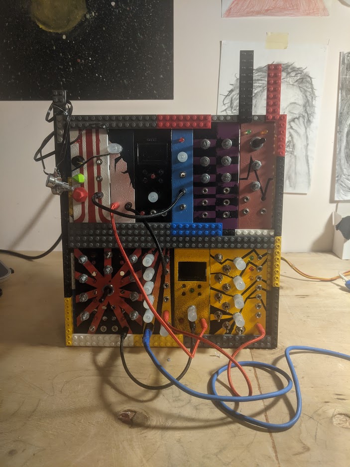
so i was curious about the reverse avalanche and now i guess i have a kind of lego-rack (of course in constant progress), so thank you all.
panels made from vinyl tiles, sanded and painted, i made knobs from fimo or cut hot glue sticks and drilled 6mm holes, so its all budget
Little update for @Jos and the other people that showed interest (can’t remember and cannot find the post, sorry)
I have not finished the guitar amp yet, but built a simple amplifier with a television line pentode according to this schematic:
I used a pl36. You can use el36 and probably all of the pl50x series.
I used a Visaton tr 10.16 100v pa transformer as output transformer. It sounds great! It runs on 24v. Bass response is a little weak but that’s also because the transformer has a cutoff frequency of 50hz, volume is also just a bit too low but that would be greatly improved with a higher anode voltage.
Edit: if you use the same transformer you may need to connect an 8 ohm speaker to the 16 ohm tap. 500-1000 ohms seems to be a good load.
Definitely give these tubes a try if you have them, they are still cheap ![]()
I am going to try with pull-up grid bias, it might help with the volume and will also raise input impedance.
Will keep you updated ![]()
Well, that’s an smart idea to remember! Maybe I can use those sticks for something like that in the future.