Starting a little CMOS synth build

Being very much an electronics beginner, I thought it’d be interesting to make a small Lunetta / CMOS synth style mini-modular as I learn more and improve my skills. I guess I’ll post here what I’m up to, see what you all think, I’m sure you will have interesting reactions. I love to post excessively frequent updates about my creative project in unnecessary detail.

I’ve been working through Elliot Williams’ Hackaday Logic Noise series, a fantastic introduction to some of the chips used to make these. The general idea is to expose the pinout of CMOS chips to the performer as directly as possible. Those chips deal with digital signals, so it’s mostly binary logic and square waves. Stanley Lunetta, after whom the synths are named, made them with banana plugs, but I’m gonna make it tiny, using pin headers and Dupont cables.

The schematics are easy to get going on the breadboard, but I wanted them to be a bit more permanent.

Elliot made PCBs for his blog post series, containing pretty much every circuit explained in the posts. So I decided to simply send the Gerbers to a PCB fab, bought the BOM, and assembled it, thread’s over, project is complete. Thanks for reading!

:wave: :dog:


Ok nah I didn’t actually do that. I’m gonna do it the hard way instead :slight_smile:

While researching the topic, I saw this video and immediately loved the aesthetic of it. All the guts exposed.

So I decided to try out using perfboard for it too, and made some 3D print tests to get a nice enclosure:

But the wiring turned out to be much more difficult than I imagined, and in addition to that, it refused to spring to life, for no clear reason.

Frankly, I don’t like using perfboard. It feels messy and dirty to join leads together. Every build technique feels awkward. Always feels like a miracle when the multimeter tells you you’re not shorting anything.

At a loss how to debug it, I decided to shelve it for now (I’ll see if I can figure it out in a month or so when I know more), and try out something easier, permanent prototype PCB that imitate a breadboard layout.

I started creating a layout with DIYLC, but that tool doesn’t really do footprints, I had to experiment with the real thing to make sure my idea would physically fit.

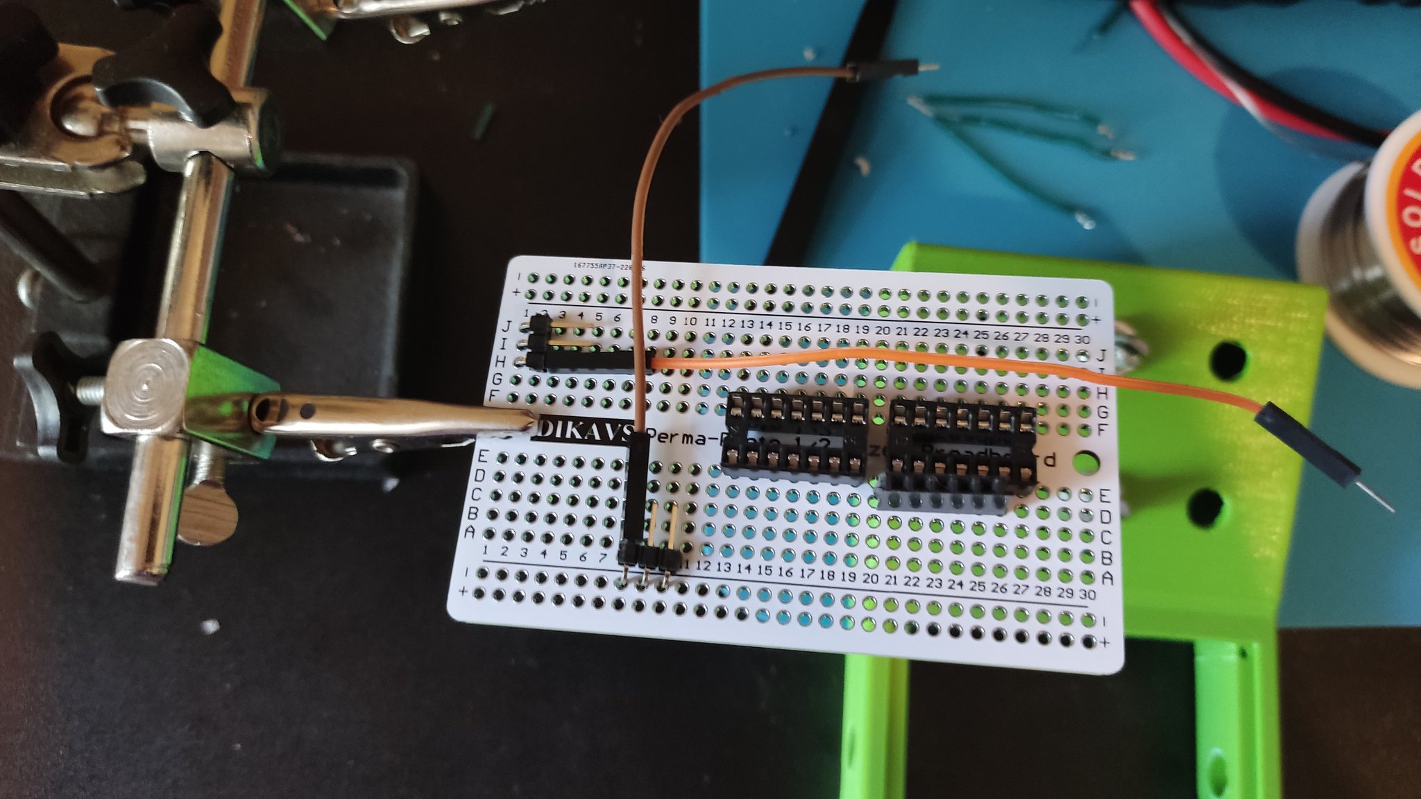
After that, I tried out my ideas on a real half-size breadboard, and wrote them down on the computer:

For this V2, I changed to male pin headers, as I realized they would make it easier to use jumpers to short adjacent pins.

A few hours and minor revisions later, I have it working! It’s not finished yet, I need to wire the pots and make it an enclosure, but you can hear it growl, it is angry:

I might have made the Blinkenlichten too powerful… Gonna need sunglasses to patch the thing. And don’t be fooled by all the gear I have, I barely understand what I’m doing yet. But I’m sure I’ll understand a lot more by the time I give this little board a dozen of friends :slight_smile:

CMOS stuff can run at a wide range of voltages, so I went with 12V for now. I can still change it, I guess, if there’s a good reason to. My thinking going with 12V was:

  • Will be easy to find a PSU for it
  • I wanna use LEDs all over the place and not sweat the power consumption so I don’t wanna use a 9V battery
  • I’d love to add a microcontroller to do… something with it, I don’t know what yet. Might be easier to go with 5V for this reason maybe?
  • 12V will let it talk to eurorack/kosmo stuff somewhat safely (provided protections from negative voltage)
  • Actually I didn’t really think very hard about this I guess

Even if I’m doing this in great part as a learning project, ultimately it has to yield an object that is musically useful. I’m not big into doing “experimental” “ambient” “drone” “noise” music. Even if I’ll get later to make an exponential VCO that will accept V/Oct, it seems to be shaping up to be the kind of beast that yearns to sing notes with no name. So I think my focus will be on making it primarily a useful rhythm machine. Not necessarily drums and percussive, but mostly about rhythmic sounds of indeterminate pitch.

Some good other resources about this style of circuit, if anyone’s interested:

Hopefully I get this first module finished tomorrow!

10 Likes

This little thing is giving me trouble.

First, those wires weren’t working out. I used reclaimed Ethernet wires, which I saw people recommend for synth stuff, but they connected poorly. I’m probably either stripping them wrong, or tinning and soldering them wrong. Either way, I went with solid core wire.

I tested the circuit and…

It’s not supposed to do that. It doesn’t do that on a real breadboard! It works as expected once I connect all the 40106’s inputs to the ground except for one, so I have a good hunch what’s the problem, but it’s really awkward to poke the circuit like this, so I’m focusing on finishing the enclosure. Once it’s mounted properly, it will easier to study what it’s up to.

So, for the enclosure, I’d like to have an array of those, as I mentioned in the first post, and this is the system I’m considering:

I’m thinking of adding M3 heat set inserts to the feet, and adding a bottom surface to the holding rings with holes suitable for countersunk screw, to be able to make a small grid of these.

I’m still very new to using FreeCad, but I’m trying to do it right, fully parametric.

(Side-note about FreeCad: three days ago, in another thread, I posted this:

And since then, just yesterday, Autodesk just announced that they are removing the ability to run local simulations from Fusion 360 — now they HAVE to run in the cloud, because screw you. And they’re pay-per use. As in, $3 per use, buy in bundles of 500 use tokens.

Yup, I will continue learning FreeCad instead of the more powerful hobbyist option.)

I picked a 60mm grid size, since that will let me use PCBs up to 100x100, the cheaper option from PCB fabs. Not that I actually know how to design a PCB yet, haha.

I’m trying to add some notes and comments to the files I create for this project, but whether I’ll share any bits of of this stuff or not will depend on the quality of the end results (and interest in it). I’m just making it for myself for now.

We’ll see how the test prints turn out!

4 Likes

“Thou shall never leave an CMOS input floating”
The are VERY high impedance and pick up almost any electrical noise…
And there is also stuff I don’t really understand, when one gate on a chip “goes crazy” the others will likely too…

3 Likes

That sure is the first thing everyone teaches you about those chips! But I’m not sure yet if it’s the actual problem, why it happens, what I did different from the schematics, and why it works on my breadboard but not on my actual build. Once the board stops slipping around the table every time I attempt to test anything, It will be easier to inspect it with my portable oscilloscope and multimeter.

(I should get myself a PCB vise… or print myself something serviceable, I guess)

1 Like

Grounding the inputs of unused gates (and op-amps) is generally good practice, not just for CMOS, but other logic types. But it’s a good idea to check chip spec sheets just to be sure, especially if the IC has complicated power requirements.

If you are prototyping, make sure you can undo the grounding easily, because Sod’s Law says you always suddenly find a use for the spare gate…

2 Likes

It is indeed a grounding issue, but I don’t think my layout was wrong, I think my build is wrong. Now that I have a decent enclosure, I could experiment a little connecting pins to a breadboard. While I have figured out a way to get most of the oscillators to work, it’s a bandaid concealing the real issue, I’ll try to understand what’s really happening before I apply a permanent fix.

As it stands, it makes a bunch of cool noises, but I want to be able to make those noises deliberately.

The mechanical design is going better than the electronics part!

This is how the mini-modules will tile together.

This button-looking piece holds 4 mini-modules together. The feet have brass heat set inserts, through which go countersunk M3 screws.

Each module + button combo takes about 25g of filament and prints in 3 hours (at high quality, those test prints are printed faster). Very lightweight, it’s not intended to be a rugged instrument to take on a world tour, lol.

I still need to revise the design a bit. For example, there’s not enough clearance for the angled headers.

The PCB themselves would be held with nuts and washers, friction alone wouldn’t keep the PCB secure during patching.

3 Likes

The 40106 module works now!

Guess what I did wrong?

I inspected my reference breadboard, which has the same design, pin for pin, as my permanent version. I saw no difference. I checked for continuity and shorts, nothing wrong.

So I swapped the chips between the two.

Yup. It worked.

Fun way to waste hours assuming it was much more likely I messed up than that I had a faulty chip.

So, the design (shown in the first post) seems correct, except I’m not sure if it’s a good idea to keep the 4069UB directly driving the LEDs. I can always snip them off later anyway. I figure I’ll make an output module with an op amp that delivers the proper levels so I have no clue if it matters. I just wanna put blinkies anywhere I think I can put one safely ok.

Anyway, time to mount it! This thing was hell to design with my current FreeCAD skills (it is not the most user-friendly program out there).

Thankfully, it worked on the first try (although the test print had some warping, so it will be discarded eventually).

Here’s a showcase of the module: VCO, hard sync, LFO.

I’ll move on to fleshing out the system and probably revise this first module design later. I made it very cramped due to a lack of supplies, but I’ve now ordered more of those breadboard layout PCBs, colored male headers, more IC holders, and 30CM F-F Dupont cables, so I can be less stingy and spread things out.

5 Likes

Gave that module its first friend today, a passive attenuator & mixer. No point having six oscillators if I can only listen to one at a time.

I wanted to make it fancier with amplification, and had such a fancier circuit working on a breadboard, but understanding op amp negative feedback still makes my head spin, so I’ll put one in a future module once I take the time to experiment with them more, and read more about the theory.

Here’s the mess in the back, with the mounting hardware. Clearances on that test model were bad, but nothing that can’t be fixed with flush cutters, a hot air gun, and a 3d pen. You can also see that the heat set inserts sink too deep into the feet, I need to make the hole smaller than their actual diameter—those little brass inserts are normally set in place by placing a soldering iron inside them, and letting them slowly penetrate and melt the plastic, bonding with it to reinforce the screw threads.

Since I’m slowly learning kicad, I tried to write down the circuit I used… Feel free to tell me if I’m doing things wrong or unidiomatically, I have no clue what I’m doing.

And the layout I used:

I still don’t like perfboard lol. The front might look tidy, but the back is a mess.

Anyway, I don’t really know what I’ll build next… Many options. I need to pick something to make this system more than a drone box ASAP. I also need to tame the harshness of unfiltered square waves… and I still need to learn what half my CMOS chips even do, heh.
I have in stock between 3 and 5 of all of these: CD40106BE, CD4040BE, CD4069UBE, CD4070BE, CD4015BE, CD4066BE, CD4046BE, CD4051BE, CD4017BE, CD4094BE, CD4007UBE, and CD4022BE.

4 Likes

I didn’t include much theory here but I made this cheatsheet with a bunch of the most common op amp configurations for building and reading schematics:

Theory wise, there are a lot of maths heavy, written-by-and-for-engineers op amp ‘tutorials’ online - they’re amazing if you already know most of the concepts but have a lot of extra fluff - IMO they’re not that great for beginners just wanting the basics to hack together a synth

I would highly recommend @moritzklein 's YouTube
channel where he designs (more traditional synth) modules from scratch and explains each component and concept along the way. Even if your noisebox isn’t built quite like a Eurorack system the VCO series is a great primer to analogue electronics.

His documentation for the Erica Synths modules are edited versions of the video scripts if you’re not as partial to videos: Erica Synths - mki x es.EDU .

4 Likes

I’ll take a look at that thread! I have checked a ton of archives here, but not that one yet.

And yeah, I’m not looking for the super detailed big brain equations, or for a solution ready to copy-paste without understanding it, I’m more trying to develop my intuition why the circuit does the things it does.

Moritz’s stuff is cool, but sadly, I am strongly dependent on subtitles to use videos: the compounding effects of having an auditory processing disorder, not being a native speaker, and the speaker having an accent can render speech unintelligible. And sadly, Youtube decided to interpret quite a few of his videos as being in German rather than English, so it’s impossible to get subtitles for them.
I watched the one about making a mixer, it includes a discussion of negative feedback, but I don’t feel I understood it properly yet.

1 Like

Just about everything you need to know about op amp circuits, at least at a basic level, boils down to

  1. Current doesn’t flow in or out of the + or - inputs
  2. If there’s feedback to the - input, the voltage on it will equal the voltage on the + input
  3. Ohm’s law
  4. Algebra (of the most basic sort — solving linear equations)

For instance:

image

V- = V+ = 0 (#2 above)
I1 = (Vin - V-)/R1 (Ohm’s law)
I2 = (V- - Vout)/R2 (Ohm’s law)
I1 = I2 (#1 above)

So Vin/R1 = -Vout/R2, solve for Vout and you get Vout = -Vin(R2/R1).

6 Likes

Another little thing today, this 4040 binary counter breakout box, it lets me play waves octaves lower, and should let me slow down my LFO enough to use as trigger sequences.

While I can see my building skills improving, I really don’t wanna make more of those little sculptures.

I forgot it’s a good idea to have a decoupling capacitor for each chip… Added one on the diagram after the fact lol. I’ll have to revise this next time in the atelier.

I have no idea how I managed to avoid shorts. Also I discovered my mixer from yesterday has a problem, one of the knobs controls the wrong channel. And I managed to get some crosstalk on my oscillators again somehow. Hopefully a build issue in both cases.

Maybe one good first KiCAD PCB project would be making my own prototype board that tiles well on my system, similar to @analogoutput’s project. I’d add footprints for PCB-mounted knobs, and a dedicated I/O zone.

The general idea I’m considering:


Disregard my using the wrong footprints and doing things the wrong way, this is just a mockup, I need to learn KiCad and PCB design more to do it properly.

6 Likes

And here’s what I’ve got so far. Learning PCB making and KiCAD at the same time isn’t exactly a great idea, but it’s not exactly like you can decouple both endeavors, heh.

I had this (possibly terrible) idea for combining two footprints at the bottom, I can put either a potentiometer or a pushbutton there.

As is the only MO I know, I have no clue what I’m doing, but here’s what I’ve got so far, feel free to tell me about anything stupid you notice, I’ll be sure to also cross-reference the design with articles about common PCB mistakes and send it to a few people who offered to take a look at my first PCBs.

At 99×99, it would be just under the magic size where Chinese fabs cut you a special deal, while also fitting perfectly in my 120×120 grid.

Oh, and here’s some footage of the 4040 screaming from earlier today:

As usual, I won’t risk recording with any decent gear yet, so it’s gonna be phone and ultra budget speakers for now.

4 Likes

One bypass 10 µF per board is plenty, but it’s good practice to have one 100 nF from each chip power pin to ground, as close to the pin as practical. (But in practice their absence may cause no trouble.)

If the 10 µF were on the other side of the Schottky the latter would prevent the former exploding.

4 Likes

Let’s hope I didn’t just make a €6.59 mistake by having those printed.

Now to wait a month on them to arrive (and probably notice a critical mistake two days from now).

In fact, I already noticed a mistake useful feature at the top of the board:
image

And the status LED has bad connections too. Ah well, I can put a blinky anywhere else. Hopefully this project was too simple to mess up the general idea. Always time for a V2.

It’s obviously very similar to this project, which I used among my references, but I didn’t want to simply use it as a base to edit, to learn to do it from scratch properly.

3 Likes

No progress last two weeks… But the PCBs are here!


Now, will they actually work?

6 Likes

This way of doing things reveals a new problem:

Because there can be wires on both sides, it’s not a problem to make things fit physically.
But this mess of a diagram is 100% unreadable. I can barely read it myself, and it’s not even 40% complete.
I could try to improve the colors, but that wouldn’t turn it readable.
DIYLC was just not meant for two-sided diagrams.

Of course, this prototype is only being built for me, but the plan was always that if anything good comes of it, I want to be able to share it, and documenting a layout a posteriori isn’t gonna happen.
So what now?

2 Likes

I have been mostly using protoboards and yes this is the kind of problem you have.
I usually try to only use the components and wires when absolutely necessary. (Unless you are also a spaghetti lover :yum:)
Also, one “advice” do not put anything on top of the ICs, it can be a massive pain later on.
Here i have got the Digisound 80 vcf and the OBA on the same board.


Good luck !

2 Likes

This is where schematics become invaluable. The schematic should be the “golden” reference, then everything else is just an implementation. Your version may be on a specific prototype card, someone else on stripboard and some one else might decide to make a PCB. Each implementation will be different, but the underlying circuit as drawn in the schematic should be the same. You can then cross reference the schematic vs the layout when troubleshooting!

Cheers

5 Likes

Look, you don’t want to know how many hours in Factorio I have.

Cool little board :smiley:

Oh definitely, I haven’t drawn one because it’s cobbled together from existing ones, but in this scenario I’m thinking specifically about documenting a working, proven layout & physical design. Well, assuming I manage to make it “working and proven” first.

Also, this is what I got so far…

It’s kind of a problem that a photo is easier to understand than a diagram. I would need at the very least support for arbitrary front/back layers, and a way to mirror the entire assembly (DIYLC refuses to mirror some objects, and mirrorring in an image editor would also mirror the letters)