Yeah one of them needs to get flipped over in Kicad so they are orientated correctly. I had it this way to visually check my alignments between panels.
The “extra” headers on the daughter board aren’t extra, one 3 pin per pot. The 3D rendering always shows male pins. The two you are probably looking at are on the front face while the others are on the back side.
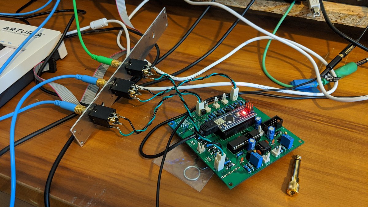
No switches on this module
How do you design the snap-seam? In kicad? I also saw JLC does some kind of auto-panelization if u set it up but haven’t looked into either.
The first snap i did by just having a line of tiny edge cut holes. I got charged extra on that as they believe it to be 2 separate PCB designs as there was no electrical connection.
The next board I just drew a silk cut line for the hack saw, but I also added a trace round the daughter board to a 2 pin header back to GND and +5V on the main board so it looked like one PCB.
The latest board I have drawn an EDGE-CUT rounded rectangle across the board to with 3.5mm of the board edge, and also added my fake traces. That seems to have passed engineering without the surcharge. Hopefully get made correctly…
I hardly ever seem to do any hardware builds. This is a prototype test with a 6.35mm jack and a 6mm potentiometer mounted on an A5 panel made of 2mm greyboard. This material is a kind of bionic cardboard, very inexpensive and very easy to work with. I made the holes using pencil, rule and a Swiss Army knife, and finished them off with the small pair of scissors provided on the knife. The downside is that it lacks the stiffness that would make it suitable for patch panels, but I could use it for arrays of knobs and display elements such as LEDs and LCD panels.
It’s really great for cheap and cheerful mock-ups before I get out a drill and make holes in something I want to endure for a long time.
I’ve added another jack and another pot, it took me about twenty minutes while I was sitting up in bed at the end of the day. I really like this material, and I’ve ordered some 3mm thick A5 greyboard samples to see if the 50% increase in thickness will make the material stiff enough to remain firm while a jack is pushed in. If not I may glue wooden battens lengthwise on the edges, as only longitudinal strain is evident at this scale. 4mm greyboard exists, I believe, but doesn’t seem to be as easy to procure.
The speed and convenience of working is really important to me. I don’t have to worry about power tools, noise or mess, or endangering the parrot’s lungs.
MS-20, SQ-10, Polisix voice board, 2xNTP 277-500 (lissajous gimmick), Doepfer Midi to CV, TR-505, CS-5. Upper and lower part are the lids of the flightcase.
Any modding tips for the sequencer?
To explain my approach further, once I’ve got a reliable methodology for populating panels quickly I’ll start experimenting with various submodular constructions that I suspect might best be classed as “signal conditioning.”
Little scraps of veroboard (or even those tiny solderless breadboards) populated with simple circuits. electronic Lego bricks. In software engineering this kind of structure is known as a “facade.” You present the outside world with a structure it can work with easily, and on the inside you translate to and from the structures the module needs to do its part.
I’m about to make my first VCO! But umm well I saw a lot of schems and all but they use all different kind of op-amps like the tl07x tl08x ne553x lm53x, so um can I use the one I want or it would make diffenrece?
Yes, modules made of bolted-together modules (which I’m calling submodules.) It’s not unlike the approach taken by CTAG with their Strämpler and TBA modules, or Bela with their Salt and Pepper modules, but ditching the monolithic builds. The idea is to build up a stock of standard parts and use them to quickly prototype new designs with a minimum of extra work, no bespoke circuit boards, and the improved testability that comes with standardisation.
I’ll probably be using this technique with Bela or ESP32 as brains, running software written in Faust and SuperCollider, and with high MIDI integration. The aim is interoperability with pure analogue modules.
It depends on the circuit, and there is no simple answer. But on the other hand, most opamps use a standard pinout so as long as you use sockets, you can always build the circuit with the “wrong” chip and see if it works and switch to the “right” one if it doesn’t; the odds that the wrong amp will damage anything are very low.
what fredrik said [ use sockets ] it is always a good idea . if you blow an IC that is soldered to the board they are a pain in the ass to get off and often times damage board .
TL06* and TL07* and TL08* are pretty much interchangeable; as I recall the tl;dr version is TL06* is lower power and TL08* is lower offset and TL07* is lower noise, or did I get those last two backwards? Something like that anyway. I usually see TL07* specified and it’s what I mostly use.