no but damn! thats a really good idea! just need to add a little brace and it will sit in there perfectly! 
2 Likes
It’s been a month since I’ve been fully vaccinated, been doing quite a lot of socializing since. It’s rather agreeable to find some semblance of normality. But between that and summer time garden/outdoor activities, the DIY synth had been rather neglected. Today I got back on the horse and kept working on my noise source - a BJT in a zener config, hooked up to a S&H, with it’s own little 555 clock circuit:
Finally sounds like a real synthesizer! - GIF on Imgur
Got to love that authentic synthesizer random bleepyness.
Next up is to build a slew limiter and feed the S&H into that, for gloopy bloops.
Cheers
5 Likes
What did you do for the sample and hold build?
Still tinkering with it, but it’s based around an LF398.
At present I’ve got a TLC555 putting out a 20ms high pulse to sample, the it goes low to hold, but I realized I’m going to have to invert all that if I want to drive it off a gate signal without having to jump through edge-detecting hoops…
2 Likes
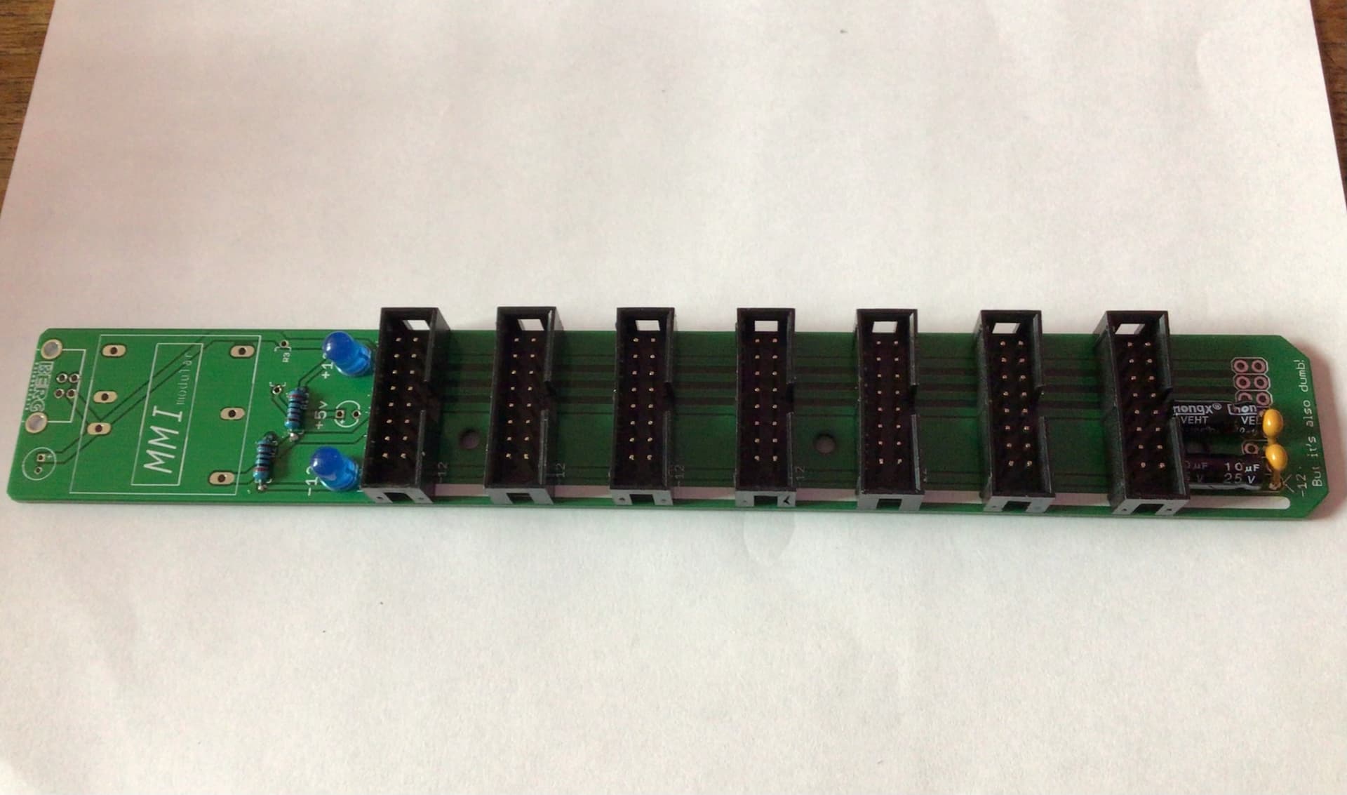
I hacked together a Buffered Mult and gave it a test. I havent worked out what I want to scrawl on the panel yet so it is still blank.

2 Likes
Did up a new rack today, as the old one ran out of space. Just a spare sheet of plywood, cut up with a jigsaw, and I got someone to 3D print me the brackets
First time using a jigsaw and I wasn’t being super clean, so it’s a bit janky but hey, it works, is currently double the space of the old one, and I’ve got room for another 3u.
Going to treat this as an experiment rack to see how I feel about the dimensions, power mounting, etc, then down the line I’ll either clean this one up, make a better one, or have someone make a nice looking one for me.

Edit: just got all the modules screwed in, powered up and tested out. What a pain in the butt! Really need to switch to threaded inserts, or totally load up the rails with nuts. Also am definitely at the place now where things would be cleaner with a proper power supply and a couple bus boards. Hopefully not too far off for that. But I’m happy to see how much nicer patching vertically instead of just horizontally is, in terms of having extra room to reach knobs.

7 Likes
I added another display to my Daisy Seed experimental / prototype setup. Now I have an SPI and I2C display and can experiment with both protocols.

6 Likes
Today I received the new set of PCBs for Wave-Multiply-O-Matic v0.2
This time round I ordered the aluminium PCB variety for the front panel I had designed. I was particularly interested in the stiffness of the material. Would it bend less easily as the normal pcb material? Well I have no way of measuring this other than to bend them by hand and feel whether there is a difference, and yes, there is. The aluminium version (which has the same thickness) is quite a bit stiffer than the pcb version.
The material looks like it is metal through and through (so not a layer of aluminium on top of some pcb substrate):

And it also makes for nice and shiny panels:
Backside:

Frontside:

Note: given its metal surface it seems well suited as a cooling surface.
11 Likes
That panel looks really nice!
If I get it correctly, there’s a copper substrate on only one side, right? So that panel backside is bare aluminium with silk screen, without any solder mask?
Cheers!
I don’t know, I only had a frontpanel made for the module I’m working on. Although I expect there to be a layer of isolating material between the copper and the aluminium; and this type is only usable for PCB designs that have one copper layer only I take it. Or are there other uses?
2 Likes
I love it! It’s exactly what we want in a front panel this is so cool.
3 Likes
Yes I believe these are mainly used for high-power LED circuits, where the PCB is basically the heat sink. There should indeed be a dielectric layer between the copper and aluminium, which is electrically isolating but thermally conductive.
Cool work!
1 Like
It also seems to be the same price as (single layer) FR4, which surprises me. At PCBWay, aluminum is 50% more than FR4: single layer 50 x 200 mm is $36 vs $24. (And PCBWay will do 2-layer aluminum, but the price goes up from $36 to $276!)
I’m surprised KiCad’s pcbnew does not appear to support single layer boards. (Maybe not so surprising, at least for THT the routing needs to go on one side and the components on the other.) You can only choose an even number of layers. So do you just make sure no holes are plated through and omit one copper layer Gerber file? Or does the fab house not care as long as there’s no copper in the second copper layer?
3 Likes
Yes, more infos !
That seems to fill the gap between PCB front panels and Front Panel Express.
2 Likes
Per JLCPCB (email response to query):
1.Currently we only support single layer board for aluminum board, i suggest you delete the file for the side without any copper, it could make us process your order more smoothly, hope you could understand.
2.Actully the single layer aluminum boards almost are similar as single FR4 boards, we only support the copper, soldermask, silkscreen on one side of the boards, so please delete all the files for another side.
3.Becuse there is only one side have copper for single layer boards, so it’s useless to set PTH, so we only support NPTH for aluminum boards.
3 Likes

My first Arduino-based module is coming together. A four channel clock divider & four step sequencer. One pot divides incoming clock by 1 to 16 and another pot selects sequence for it. The four leds next to the output jacks aren’t just wired to them to show then trigger is outputted, but they are on their own outputs of Arduino. So, when turning a pot they momentarily show in 4-bit binary what is the value of the pot. And in sequencer-pots, the binary value is directly the sequence. Also, the outputs have diodes on them, show they can be added, or Logical ORed, with passive mults or stacking cables.
8 Likes
I’ve managed to get some simple midi CC control to work on Vocode-O-Matic. I can now shift the modulation matrix or choose one of the 6 build in matrix layouts using midi CC in real time.

5 Likes
Nice! Any chance you will be uploading a schematic?
1 Like
Fantastic! Did you do the PCB layout yourself or is this from somewhere else?