Sculpt-O-Sound presents “Vocode-O-Matic for Daisy Seed”
Summary
Vocode-O-Matic is a real time 31 terts band vocoder with a pseudo stereo output which runs on Electro-Smith’s Daisy Seed. The code is running fine and midi support will be added soon, furthermore a real time spectral display is planned.
I have not yet decided on what the front panel of the module will look like nor have I designed a PCB yet, so I’m open to suggestions and collaborations !
Introduction
If you don’t know what a Daisy Seed is, have a look here: Daisy – Electrosmith

It is a fast microprocessor on a small board combined with some RAM and a quad ADDA-converter. It can be powered via USB and you can program it in C/C++.
I’ve got the vocoder running on the Daisy Seed and I’m happy to say that it sounds great!
Currently I am still working on midi control and a spectral display. Once that is finished it can be modelled into a euro and/or kosmo format model. For the moment the Daisy is running from a simple vero board that I soldered some connectors to so that it is easier to program.

If anyone wants to help me create a PCB for the Daisy, do let me know!
What is a vocoder?
There are countless texts on vocoders, but as the idea behind it is not very complicated ( the sonic effects one can achieve with it, are! ) I will try to explain it briefly.
Imagine we have a signal, e.g. a string chord. The string chord has its own timbre which means it consists of all kinds of tonal components each at their respective amplitude. The string chord is the sum of these tonal components.
Have a look at schematic 0.

Imagine we could split the signal into those tonal components and play with their amplitude before summing them up again. That would possibly change the timbre of the string chord in an interesting way.
Well, that is exactly what one half of a vocoder does. It splits a signal called carrier into several bands using Bandpass Filters (BF in schematic 0), sends each one of those through a VCA (voltage controlled amplifiers controlled via CV1, CV2, CV3) and sums the output of those VCAs and sends this result to its output.
In stead of playing with the control voltages of the VCAs using potentiometers a vocoder derives those voltages from the other half of the vocoder circuit. In fact it gets the tonal contents from another signal, called the modulator. Have a look at schematic I.

The modulator signal is split using band pass filters as well. The output of each bandpass filter is send through an envelope follower (ENV), a circuit that traces the contour of the signal’s amplitude it is fed. That contour changes relatively slowly, it is as it were the rhythm of the modulator signal in that frequency band. See picture:

The yellow line shows the waveform, the black line the output of the envelope follower. Note that the envelope follower can be made using a simple filter which has an certain attack and decay time.
So now if the envelope follower outputs control the VCAs, then the variation in amplitude of the tonal components of the modulator will control those of the carrier. So there you have it, a vocoder !
But there are more possibilities here.
Say in the schematic the band pass filters have the same frequencies and bandwidths for the 3 bands of the modulator and the carrier and we link the low, the mid and the high band envelope follower output of the modulator to the respective low, mid and high VCA of the carrier, then we have what I would call a linear modulation matrix.
So how does this sound? Well in case of a drum loop as the modulator and a string chord as a carrier one would hear the chord change to the rhythm of the drum loop without hearing the drum loop.
Modulation matrix
What would happen if the modulator stage and carrier stage were not hard linked? What would it sound like if one were to link the low, mid, high to the high, mid, low VCAs? This I would call inverse frequency band modulation. This would sound rather different than the prior example. The chord will change to the rhythm of the drum loop, but the changes sound like they are “stretched in time” more or less (an audio example will clarify this later).
There are lots and lots of other modulation connections that mayl sound interesting. A flexible vocoder would e.g. allow for any possible connection between the modulator band outputs and carrier VCA inputs. This is why vocoders often have a patch area or connection matrix or modulation matrix (see schematic II).

So far the matrix was presented as a set of connections, but in stead of on/off switches, you could imagine those to be potentiometers, couldn’t you? This would allow for some modulator bands to have a small effect and others a more dominant effect on the carrier.
On the other hand that would result in 9 potentiometers for 3 modulator + 3 carrier bands. A simpler but effective implementation would use switches in the matrix and add an output level stage to the envelope follower of each modulator band.
Modulating the modulation matrix
And why stop at using potentiometers to select the effect of a modulator band on one or more carrier envelopes? One could imagine that based on an external gate signal, all connections would e.g. shift one position to the right in the matrix ( with wrap around ).

Or based on a gate signal the whole matrix of switches would change from linear to inverse or some other configuration? If you sync this to a beat or start of a bar this can sound really good.
Stereo
There is a neat trick to turn the output of a vocoder into a pseudo stereo output. When adding a panning stage to the output and panning the odd carrier VCA outputs slightly to one output and the even carrier VCA outputs slightly to the other output one often gets a nice spacy sound! Obviously this depends on the tonal contents of the carrier and modulator signals (and the number of bands) to sound good. Have a look at schematic III.

Implementation
Some of the things mentioned above can be easily implemented in hardware or executed in the physical world, for others the cost would be prohibitive. But in software all of those can be implemented quite easily on a fast processor. The Daisy Seed (from electro-smith) has one such processor (400 Mhz) and AD-DA facilities (for USD 29, last time I looked).
Vocode-O-Matic for Daisy Seed
Vocode-O-Matic for Daisy Seed is the software version of a 31 ( yep, not 3 but 31 ) band vocoder (each band is 1 terts wide) written in C. It has the same core as the version I published earlier for VCV-Rack, see screendump of VCV below:

The version of Vocode-O-Matic for Daisy Seed knows 6 pre fabricated matrices (4 log versions, 1 linear, 1 inverse) and can either shift the matrix or swap it for another one on a trigger. Panning is implemented so that the odd bands and even bands can be positioned in a stereo space. The energy levels of all bands is computed, for the carrier and modulator signals and also for the left and right output signals, so that the levels can be displayed on a screen ( still to be developed ).
The filters are shift registers in a so called Direct Form I topology (so no DFT and windowing is done) and are based on the series of tutorial papers about Effect Design by Jon Dattorro published in 1997 in the Journal of the Audio Engineering Society. Jon Datorro designed most of the audio effects from Ensoniq Corp. between 1987 and 1995.
The filters cover a range from 20 Hz to 22025 Hz, the sampling rate is 48 kHz. Their central frequencies are based on an auditory scale.
Audio examples
I do not so much care for using a vocoder with speech so I will leave it up to you to experiment with that. All examples I made are some drum loop as a modulator combined with a carrier with a relative broad spectrum. Have a listen at these examples:

A broad spectrum will increase the odds of the vocoder outputing anything since there is likely an overlap in frequencies between the modulator bands’ content and the carrier bands they are modulating.
Over the years I’ve used the vocoder in quite a lot of my tracks. You can hear an example here in which the lead strings are modulated by a vocoder and the matrix is shifted throughout the track, which in a blinding moment of inpiration got me to name the track ‘Shift’. Another example of extensive use of the vocoder can be heard in the track ‘Japanese Love Song’ which is part of a demo video which you can find here:

Even the drum samples were produced using the vocoder. I used one drum loop as a modulator and another as a carrier which lead to the “doesn’t it sound like a washing machine which load is unbalanced?”-kinda rhythm.
This track is quite old and the vocoded sounds were made using a file based version of the vocoder that preceeds the real time version described in this thread by about 20 years. That code runs on Linux and OSX and its core code was used in the present real time version.
If you listen to the song keep in mind that ALL rhythmic string like sounds you hear throughout the track were produced by the vocoder with a single string sample and a drum loop as input signals and lots of variations of the modulation matrix.
Input signals
The vocoder will only produce sound if the carrier bands that are modulated have some signal content and if the modulator band envelopes that do the modulating have some content. If there is a mismatch, e.g. one of the carrier bands does not contain any signal, then that band will not contribute any sound to the summed output. Similarly if a carrier band does have some signal in it, but it is not modulated by a modulator envelope because that lacks any signal, it will not contribute to the summed output. So the resulting output signal heavily depends on both signals.
As a rule of thumb: if you use a carrier signal with a broad spectrum, then any modulator will be ok to get some output signal. If the carrier signal only occupies a narrow part of the audio spectrum, then you need to either find a fitting modulator or construct the modulation matrix in such a way that some of the modulator bands’ envelopes will connect to the carrier VCAs that cover that narrow part of the audio spectrum in order to get some output signal.
Tip: try to modulate a drum loop with another drum loop and shift the matrix. This will sometimes result in extraordinary rhythms.
Current and future developments
Speech
Vocode-O-Matic does not have a voiced/unvoiced detector, so when used with speech you are likely only to hear the effects of spoken vowels and not of consonants. In other words, using speech will not likely lead to intelligible results. But your mileage may vary. Maybe in the future I will modify the vocoder to adapt it to processing speech.
Spectral display
The envelope follower output of each modulator band is proportional to the energy in that band over time. So in an earlier version of the software that ran on my PC I added a display which shows that energy.
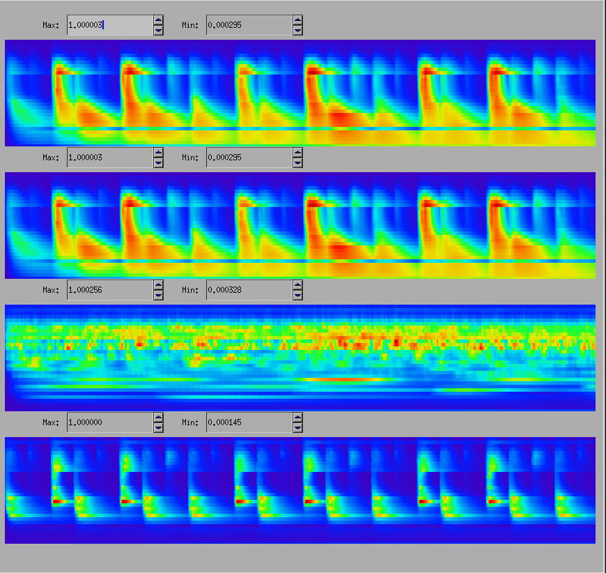
Here in the bottom panel you see the energy over time of the modulator sample, in the 2nd the energy over time of the carrier signal and in the top 2 panels the resulting energy over time in the left and right output signal.
In the current implementation of Vocode-O-Matic not only the envelopes of the modulator signal but also the envelopes of the carrier bands and the bands that constitute the output signals are computed to obtain energy readings of all signals. So I’m thinking of adding a real time display showing those. See the picture above. The bottom panel shows the spectrum of all 31 bands for the modulator over time ( the horizontal axis shows the time ). The second panel shows the carrier band energy and the top the energy in the output channel (summed). I’m currently looking into adding a real time display of the energy levels to Vocode-O-Matic. This display should show the spectral energy in the signals scrolling by in sort of a waterfall display. The display should make it easier to control the vocoder and help you grow intuitions on how to mould the sound output, and it looks great I think.
In this example you can see that there is a distinct relationship between the occurrence of energy in the modulator signal and the left and right output signals (but only if the carrier signal contains energy in the respective bands at the same time).
Midi support
At the moment of writing this thread Electro Smith is still working on Midi support for the Daisy libraries, so changing the parameters of the vocoder via midi is still in the works. B.t.w. those parameters are:
2 * 31 filters * 2 (center frequency and bandwidh/resonance)
31 * envelope follower attack time
31 * envelope follower release time
31 levels for the modulator envelope follower outputs
31 pan settings
31 * 31 matrix switches
which (depending on how these are implemented) amounts to about 1209 parameters …
The number of parameters is rather big and I’m not sure if it is worth my while to implement commands for all of them.
Maybe you have a suggestion which ones you would want to be controllable via midi or accessible via a knob on the front panel of Vocode-O-Matic?
What do you need to run Vocode-O-Matic?
You need a Daisy Seed by Electro Smith and some circuitry that will adapt any input signal to stay within 3 Vpp and some output circuitry that will amplify the Daisy’s output signal to euro rack signal levels.
There are a few options to achieve this. Either design and build your own circuitry OR have a look at the github repository where Electro-Smith have stored the open source hardware design of the Daisy Pod ( a small board for experimenting with the Daisy Seed ) or the Daisy Patch (euro rack compatible module) and design your own PCBs OR buy either the Pod (79 USD, 2nd Oct 2020) or Patch from Electro Smith (329 USD, 2nd Oct 202).
I have not yet decided on what the front panel of the module will look like, so I’m open to suggestions and collaborations !
If you want to experiment with the VCV-Rack version of Vocode-O-Matic before going for the hardware version, have a look at the VCV-Rack library or my github repository.
Build release
I will release a version of Vocode-O-Matic for Daisy Seed as soon as the midi code is integrated and stable. I have not yet decided on what the front panel of the module will look like nor have I designed a PCB yet, so I’m open to suggestions and collaborations ! Maybe this could become a community build?


