Royal Air Force tag? That’s pretty neat. I got some similar (albeit probably not of quality) “aircraft toggles” from tayda with red leds in the switch.

3 Likes
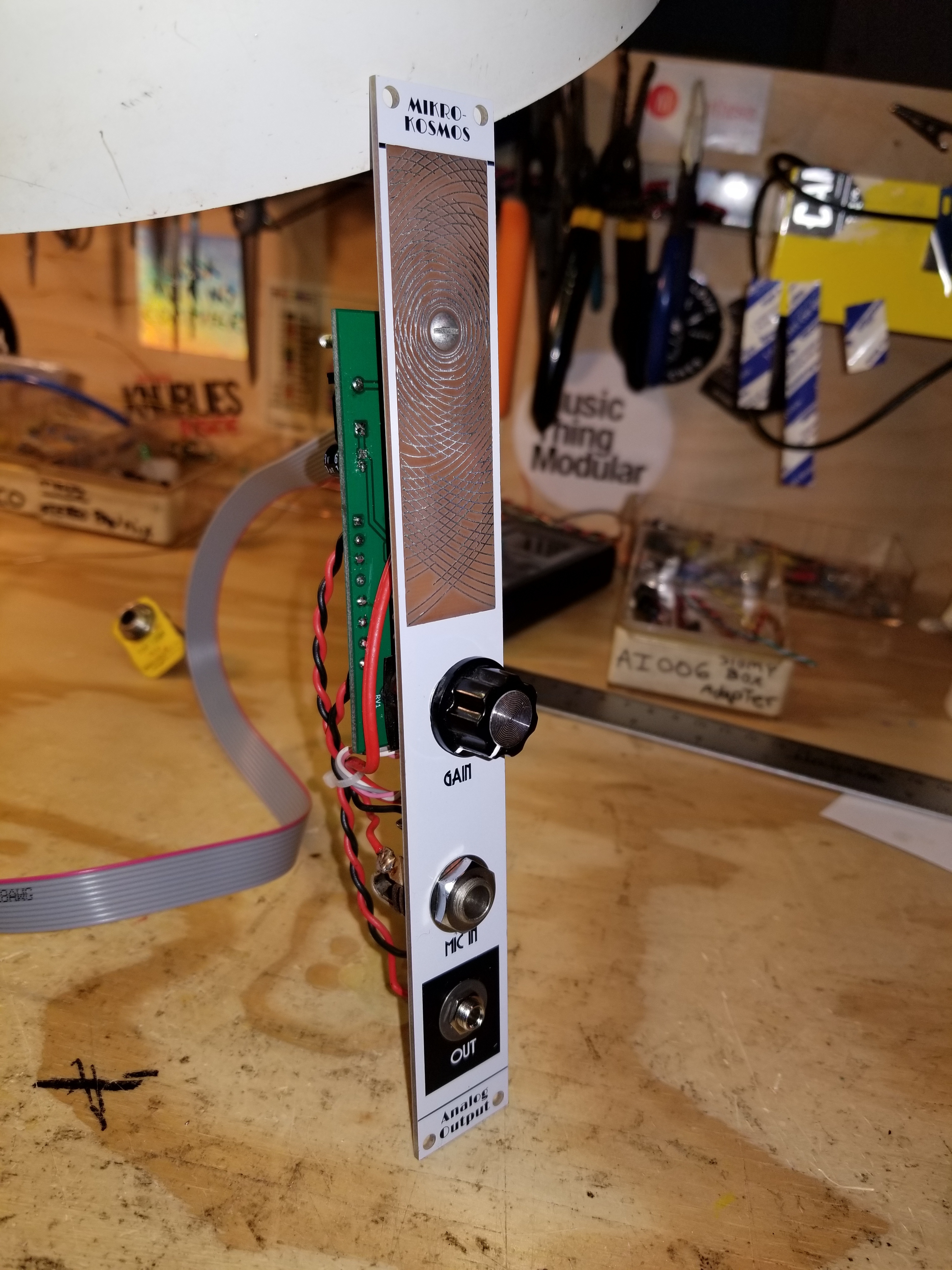
Dude, the size of it - is it to control jet power in planes? : D
1 Like
the pcb is 20mm X 175mm for a standard panel 25x200. it’s a two part board with the ( balls just realised a minor mistake) daughter board for the pot… will sort out some images later.
2 Likes
After blowing up one capacitor,resoldering 3 times half of the components power supply works stable for +/-12V and +5V. Yay!
So, next are power sockets.I do not have strip board, only this one with holes. I took sire to connect pins, but I have to do this job 3 more times - any protips how I can make it faster?


Thin wires are for CV and Gate only - as you mentioned, probably will stay unused.
1 Like
Not at all bashing on ya friend, but may I suggest some Flux?
I highly suggest getting something like a Flux Pen or a syringe of Liquid Flux
6 Likes
I really think you should buy some veroboard. The strips make your life 100x easier than what you are currently doing.
7 Likes
I agree with Al4critous for the stripboard and also the soldering is very important for the conductivity, especially there it is for the power.
without wanting to be rude some should be redone

7 Likes
It might seem like a pain to redo, but you will not regret doing it.
7 Likes
Thanks all guys!
It looks worst in pictures due the high contrast, however it is not pretty job at all. I found stripboard in my country so will order today (funny thing, I do not see that any store user particular “strip” or “stripboard” - in English or my language at all what made searching a pain).
I tried to use had rosin and flux for cables that goes into PCB - helped, however, still facing some issues with current solder, cant find proper temperature to work with, now set at 370 Celsius.
Another questions for the cables - I used 24AWG here, but it would be much easier working with strip cable. I have spare SATA cables, are wires from there will be thick enough?
After checking if there is no any shortcuts this will be only prototype board for checking modules for next 4-6days, next go with proper stripboard soldering.
3 Likes
Also goes by Veroboard.
If it helps, this is what i get:
BIG STRIPBOARD 110X93MM (COPPER)
https://www.taydaelectronics.com/big-stripboard-110x93mm-copper.html

I know i really push tayda a lot, but its for good reason.
5 Likes


Just made this Dual VCA circuit adapted from Sam’s schematic to be a little smaller to fit in my Eurorack case… and it works!!! I used Eagle for the first time to build it and it went pretty well. I just got the pots setup backwards but that’s an easy fix… Thanks @lookmumnocomputer for the schematic and inspiration to make projects like this a reality!!!
9 Likes
Looks great, nice and clean!
4 Likes
yep that can be pretty nerve racking experience sometimes .
3 Likes
yes, I have not all the components for my new power supply, and i have 6 or 7 modules finish and ready but not yet tested
… I hope everything will work the first time 
3 Likes
yeah thats always the hope , to bad it doesn’t work that way . but it does make it special when they do work on the first try .
2 Likes
Ooooh. So close. Everything seems to work (aside from a trivial software issue) except… I misconnected the output op amp. I can bypass the op amp and have something that’s sort of usable at least for testing, but I’m gonna have to do another version of the board.
4 Likes
As someone once said…
6 Likes

How did you attach the piezo?
3 Likes