I think if you ignore it, it won’t create the PCB view. But I’ll try your method soon when I feel the urge to create a PCB again. Thx
Huh? Why would you not want to clearly identify the supply rails in the schematics? I’m clearly missing something here ![]()
It’s not the identification of the supply rails, it’s an additional flag that says “this is a power rail”.
This fails rules checking:

This passes:

2 Likes
Ok, that’s not an EasyEDA thing. Google tells me it’s KiCad magic – if you do that, it’ll wire up the component supply pins all by itself, at least if you use components that are configured to use that.
(which seems somewhat pointless since you usually want decoupling caps, or can it autogenerate those as well?)
Not sure what they mean by that — certainly if I add a TL071 to the above and don’t connect +12V and -12V flags to the power pins it complains. And if I do they’re regarded as connected to those power rails, with or without the PWR_FLAGs.
If there’s an actual use for PWR_FLAGs other than to make the rules checker work, I don’t know what it is. Of course maybe I should RTFM.
Google sent me to something called “KiCad like a pro” that says that components can have hidden power pins, and
Hidden pins are… hidden because KiCad expects that somewhere in your schematic are nets that are marked as power nets. In the background, Kicad will automatically connect [hidden pins] pin 8 and pin 16 to those nets.
This discussion
makes no mention of hidden pins. Instead it explains that the rules checker wants any power input pin to be connected to a power output pin. +12V and -12V and GND are symbols for components consisting only of a power input pin. Not a power output pin, because then you’d have multiple power output pins for the same rail, and the rules checker doesn’t allow that, it wants only one output per rail. So if you have an external power source, meaning you have power coming from somewhere that isn’t in the schematic, you have to add a PWR_FLAG which is just a component consisting of a power output pin.
As for the above “hidden power pins” discussion, I dunno – when I look in the KiCad library for the 74HC595 symbol it’s different than what they show and does not have hidden pins. If I copy that symbol and hide the VCC and GND pins, and then create a PCB, those pins get connected to the VCC and GND rails in the ratsnest regardless of whether those rails have PWR_FLAGs or not (and regardless of whether those pins are hidden or not). But it fails schematic rules checking without the PWR_FLAGs.
So I think PWR_FLAG is irrelevant to such pins, or at least no more relevant than for any other power pins.
I ran into this error too for the first time with kiCad and had to add the PWR FLAGS to the rails in order to clear the rules checker. Didn’t have this error on certain schematics but then received it on others so I can’t find a clear reason why it gets triggered on some schematics and not on others?
1 Like
Cannot trust the pros, you say? ![]()
A bit more googling says “hidden pins” is a legacy thing, kind of:
Another special case are invisible power input pins. They are global labels. This is how power symbols are implemented in kicad. Do not use invisble power input pins in any application other than power symbols as they restrict how you can use your symbol. (The use of multiple power lines becomes impossible. Review of a schematic is hindered by connections being invisible.)
(from here, the link there says the 74xx library used hidden pins in version 4.)
That doesn’t really explain why you need to add them if you don’t use hidden pins, but maybe there’s some hidden stuff hidden somewhere where you’re not seeing it?
You need them because you need your “+12 V” symbols (etc.) to connect to a power output pin. Rules checker cries unless every power input pin connects to a power output pin, even if it’s a PWR_FLAG which is a power output pin that doesn’t really connect to anything inside the schematic that outputs power.
I have never seen an error for a power_flag, admittedly I have not used the ERC much as it seems to generate errors that don’t exist and you spend ages trying to fix them…
The errors you get don’t mention power flags, they’re like
ErrType(3): Pin connected to other pins, but not driven by any pin
@(9.400 in, 2.600 in): Pin 1 (Power input) of component #PWR020 is not driven (Net 49).
and pointing to some some arbitrary point connecting to a rail, so it looks a lot like “errors that don’t exist and you spend ages trying to fix them”. Once I put power flags in I don’t get errors that are not real problems.
1 Like
So is the issue that the pins on your IDC connectors aren’t configured as power out pins, or (for the 12 V rails) that the diodes are hiding their power out status?
So when do you need power flags? You need a power flag to signal to ERC that a net is powered even if there is no direct connection to a symbol pin defined as power output. One example is if you supply your pcb with a generic connector. Or if you have a passive component in series to the power supply (a fuse, the inductor or resistor of a filter, …)
(my bold) (from here, which links to an FAQ entry about “ErrType(3)”)
Fixing the output types and/or adding a “polarity protection” diode schematic (or two, even, depending on direction) would fix this. You could use a custom “diode or 10 ohm or ferrite bead or jumper” silkscreen footprint for the latter.
Both, really. I do have a custom symbol for a power header and I’ve just changed it — the pins were passive, now one of each of ±12 V and ground are power outputs, the rest are passive. (Again, you can have only one power output pin per rail.)
But then there are diodes on the ±12V rails which make the power flags necessary. Unless, as you say, you use a pair of custom 1N5817 symbols — one with the cathode as power output, one with the anode. I tried that and it mostly works. One drawback, though, is that KiCad then regards these parts as different from each other, and from standard 1N5817s, and so they do not get grouped together when you generate a BOM. If they were 10R resistors or fuses or ferrite beads you’d only need one such special symbol, and they’d get grouped together in the BOM, and there’d likely not be any other standard symbol 10R resistors or fuses or ferrite beads for them to not group with, so that’d be all right — but I use diodes and I’d rather have my schematics reflect my preference. So I guess on the whole I’d rather use power flags with standard diode symbols. At least with the revised header symbol I don’t need a flag on the ground rail.
Wow! Been off for a while and as expected too many wonderful builds. Well done !
I hope to back to posting in a week or so and up and building by mid June.
Best to all x
5 Likes
Papa? 
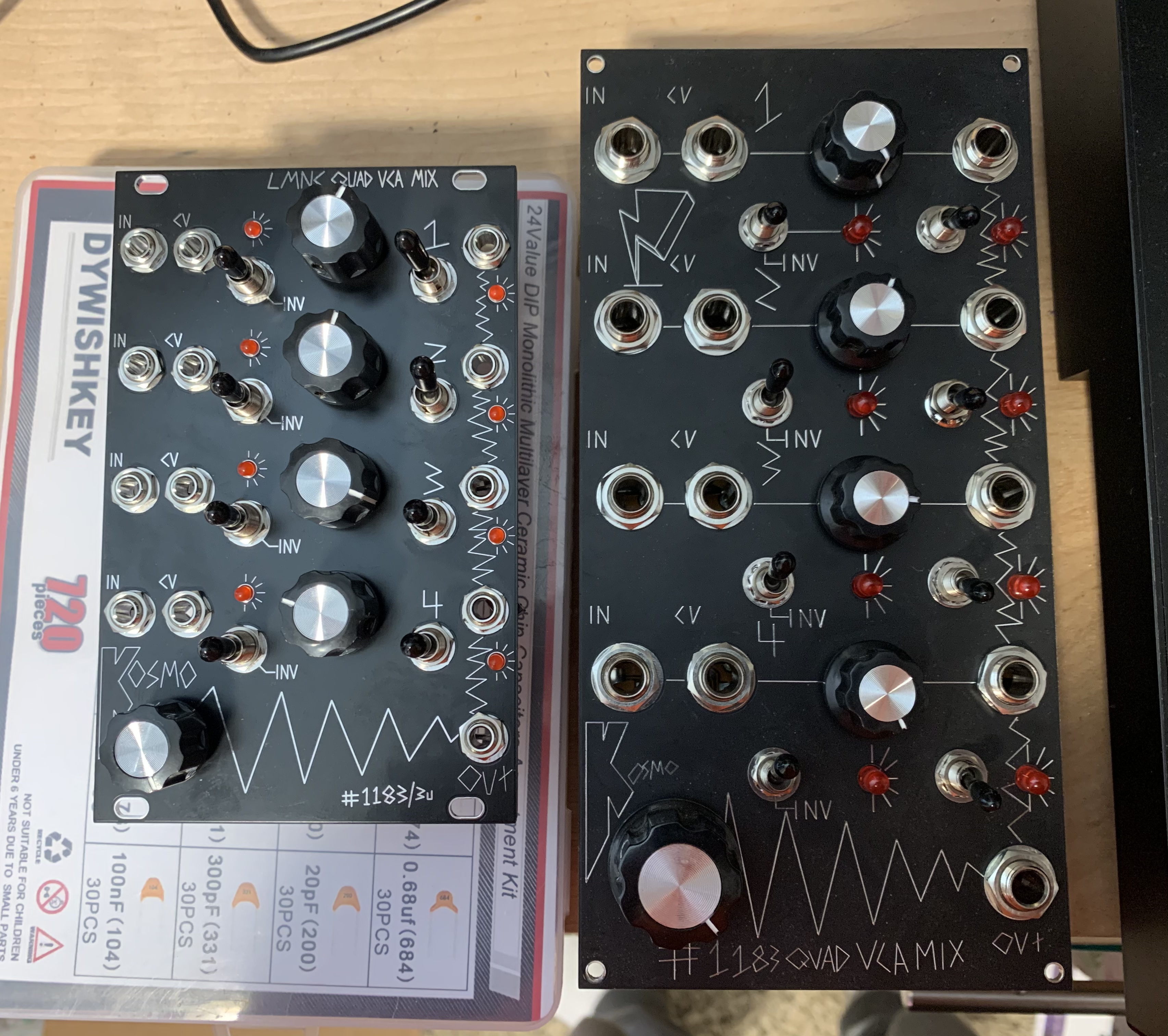
Eurorack #1183/1184
Figured my most used Kosmo module also needs to be in my eurorack. Was pretty lost without it
17 Likes
This made me do a double take.
5 Likes
ahh thats cute , wee little module …
4 Likes
Now try making a Euro scale version of the Fartbox 
3 Likes
so damn cool  …
…
2 Likes