That’s great ! I’m very interested in the display thing. I’m an absolute Arduino noob, I can blink and copy code :). And Hello World, I’ve already done it on a display :). At the moment I’m a little dissatisfied with my modular synth because I don’t have a proper LFO and then I came across the Arduino thing and see great potential in it. We’ll see, today I’ll try to build @HAGIWO’s LFO first.
1 Like
Thank you. I am also a beginner who display “Hello World” in October 2020. I hope you enjoy my projects.
5 Likes

Straight @ work on the Sync LFO !
Can you please tell me where i can find the Schematic for the GLITCH&DLY Module?
And a little “luxury request” could you please create a BOM for your projects, that makes it a little easier for beginners like me.
Otherwise I am really fascinated by your modules and hope to be able to build some in the near future.
Greetings from Germany
THOGRE
1 Like
Is your module held by a vise kinda thing that can rotate somehow?
Looks like a PanaVise 350 or similar:
https://www.panavise.com/index.html?pageID=1&page=full&--eqskudatarq=5
1 Like
I’ve always wondered whether these kind of contraptions are really helpful in general work. It’s probably a matter of getting used to.
I’ve been using some pieces of marble I found in the road some time ago. They can be used to hold things down (I use gaffer tape for that too) or up in various ways.

1 Like
Glitch and delay
refer to below page.Thanks!
3 Likes
oh please tell more about these modules, have I missed something here?
The waveshaper and pll?
This one ?
Cha-chiiing! 10 points to fredrik =)
Its a very nice vice, theres a bunch of different mounts for different jobs. (I still just use the stock one)
It might be a bit overkill for what I do as a hobbyist. I could do just as well with a standard pcb vice or a mound of blu-tack I reckon.
The same could be said about another guy I know who uses his panavice to hold locks for picking practice =D
Honestly though, I see my hobbyist ways outliving a plastic vice, may as well get something id struggle to break, even intentionally.
Its nice n heavy too, so no way its going to topple over holding a module.
Those are by @telec16. There’s some discussion starting here
GitHub repo here:
1 Like
thanks! I’ll look into it.
Since the 47nF ceramic capacitors turned up, I couldn’t not wire up the tone POT. I swapped a few of the electrolytic capacitors while I was at it, so out went the 47µF, then I shunted the 22µF and 2.2µF along one, then added a 1µF.
I think the 22µF need to go too, so will have to add some 10µF or similar to the next component order.
2 Likes

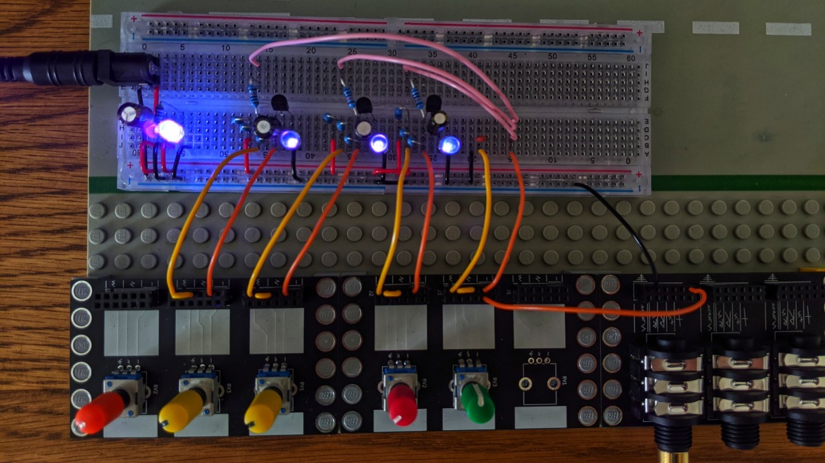
It works, unfortunately it doesn’t sound quite like the one from @HAGIWO. The waveforms don’t look that clean, the LED doesn’t work and the Arduino doesn’t work with the 12v from the PSU either, so I have to tinker with it again.
1 Like
Well, it should. You may want to have a look at this:

and maybe read this:
It describes how you can use 6 to 20V to power an arduino. Mind you, this only works from the right pin, the one marked as ‘VIN Pin’. But it is wise to keep the input voltage low, to reduce the power that needs to be dissipated by the DC regulator.
3 Likes
The new single row is filling up fast. Now I have a good range of modules from folks here. Thanks @analogoutput, @d42kn355, and @CTorp. Top notch modules. Hope to get more from y’all.


12 Likes
this may coax me into fixing the tiny errors on the xfade VCA.
unless you dont mind doing some fixes? lol - i have a few of em just sitting here.
been wanting to see them in peoples racks.
I think me, @CTorp, and @ChristianBloch are the only ones that have em.
Christian seems to have issues with his, but mine and corys seem to be workin fine.
2 Likes
I don’t mind fixing errors if there are good instructions. I’m def game to pick one up. Somehow I missed that one or i would have pinged you by now.
2 Likes
…or in a lot less words and fewer ads ![]()
3 Likes
Yes, I know that, I’ve already operated it a few times via 12v via the VIN pin. Maybe I have a cold solder joint, I need to check it again. I don’t know why the LED doesn’t light up, I took a 39k instead of the required 33k resistor, but that shouldn’t be a problem, I think, if at all only the LED should light up a bit less.
I also looked into the code again, actually it shouldn’t be that difficult to create your own waveforms, in principle 0 is the lowest point of the wave and 1000 is the highest. If you let them go up from 0-1000 you get a ramp. If I got that right. I have to try a little.