Yeah, that was as much “with the somewhat arbitrarily chosen component values I used for this test” as “I’ve verified that you can get close, and there is no unexpected hidden headroom issue” – I mean, the shunt doesn’t even know what the supply voltage is, so what would that be, but we’re in a subthread about a commercial product using an LM317 in a weird way and people that would notice if it didn’t work telling me it works great, and I’ve only used the TL431 with tiny currents before, and the datasheet mentions a 2.5 V minimum headroom, so not going to take anything for granted 
(and yes, (11.2−10.6)/100 = 5+1 mA so things do work as they should  )
)
I still think the 10.6 V rail’s power requirements are very low, based on my experiments with a non-regulating LM317-based supply where even a small load resulted in drops well above 1.4 V, so odds are e.g. 470 ohm (0.9 mA at 11.5 V) or even 680 ohm (0.3 mA) could work.
2 Likes
a reply to a previous comment first.
- The transistor outputs (gate signals?) will be limited to about 4.4V in that emiter follower configuration, is that high enough to trigger most envelope generators reliably?
Edit: 3.8V, with the 1N4148 drop.
realised last night minimum component solution would just be a voltage follower and protection resistors, no voltage drop, basically the same as you were saying but less an extramc14504, plus yes I guess its less snipping of component legs, 2 opamp packages instead of 50 component legs.
2 Likes
Well, actually … while cogitating about this circuit, I made the unfortunate mistake of consulting the data sheet for the LM7812 which is commonly used in Kosmo and Eurorack power supplies, including in the Frequency Central power supply, and I found out that the minimum voltage that it might put out is 11.5V so in theory we would have to design to that constraint.
you guys together seem to be tearing apart the fabric of the eurorack community at the same time as solving this voltage reference issue!
First of all thanks to you two, ive been catching up on some well needed, “fill in the blanks on rather patchy know how”, searching various aspects of the chat and getting to the bottom of this.
The current draw from the Vdd reference pins of the ms14504’s, I just went to test this, needless to say the only midimuso I have sitting here has been pilfered for parts much to my dismay. in the words of terminator (who most definitely had headroom for his voltage reference) i’ll be back.
But with a small enough series resistor I believe the TL431 based circuit can handle a dropout of less than a volt.
Antoine this is indeed what I have been working to this whole time. To be honest I assumed because such a large bulk of modular supplies have 7812’s I thought everyone was working towards 11.5 anyway it was just a round up. Even the deeper supplies are around that amount.
3 Likes
I suspect flimsy wiring also contributes to voltage drops (10 milliohm here, 20 milliohm there, …) which is why you can find corners of the synth internet where people insist on massive copper bus bars, etc.
(but while I think modern manufacturing, normal distribution, etc. saves you from worst case specs most of the time, I’m quite happy that I’m using a power supply design that can be populated with either 7812s or 317s – the latter is not just a better regulator, it also forces you to actually look at the voltages when you trim it…)
“fill in the blanks on rather patchy know how”
As long as you don’t forget the “don’t be scared to try it” bit 
(I have a lot of respect for the “this seems to work” approach, especially when it consistently produces results; I just occasionally run into things where I don’t quite understand *how* they can work, which sometimes means that my understanding needs refinement, but sometimes means they actually don’t work, or at least don’t do what the designer thought they were doing  )
)
3 Likes
Oh snap I just saw this. So the Prophet 600 breaks down a lot? That sux! It is at least half again your own age though-you can’t be too hard on us relics!
Can you give us an elevator pitch for what you have in mind?
1 Like
right so I have been doing a bit of playing sending to do as much as it can functionally, I am getting a current draw very small, its between 0.02 and 0.03mA (nothing else with more resolution) I thought maybe thats a bit small but, checked its all in order and thats what it is. thats a measurement between the 317 to the MC14504’s.
So to be honest the best solution that I think im going to give a go when they arrive is the suggestedTL431 , I guess the question is with the above reference voltage consumption readings, first of all does that sound at all realistic? its got me thinking its a bit low, however thinking of its function within the chip that its just using that reference into some pretty high impedance environments, maybe not??? also everything is buffered… so possibly??? but I digress, if this is indeed correct what sort of load resistor would I be looking at .
and as for the motto don’t be scared to try it indeed! it is indeed a productive way to learn and stumble upon interesting things… but yeah getting this reference voltage right is necessary! definitely a “this seems to work” motto with most things! but this module would be nice if it was in tune haha.
2 Likes
hold up im being a plonker! I knew it wasn’t right, got a new meter last week, different layout to my old one. no matter what is functioning it keeps a stable 1.3mA
2 Likes
Ok, I’d try 680 ohm 270 ohm in series to get a small margin, and a 5k1 resistor + 5k trimmer in the divider, to put the right position near the center of the trimmer.
(270 ohm gives you at least (11.5−10.6)/270 = 3.3 mA which is 1 mA for the TL431, 1.3 mA for the circuit, and 1 mA to spare. 330 ohm could work but then it’s getting a bit tight at 11.5 V)
EDIT: 220 ohm is probably better, since current is flowing through 5k+5.1k as well, see here.
2 Likes
haha max yes of course! the prophet dies all the time and im just after a simple poly to take on tour. with shared voice modular inputs, which is totally possible. its gunna be midi in for the notes and main env generators. VDO’s which are proving pretty stable without complicated autotune circuits. 1 per voice with a sub, so itll be like having a analog/digital wavetable hybrid. then just analog filters based on polys of old. most likely a 4 voice to keep DIY building to a minimum (mayyyybe 6), but it will be chain able for 8 voices. only thing in my way is finessing a filter for it, my attempts at the gameboy megamachine one is too complicated wanna keep part count as absolutely low as possible.
2 Likes
ok well thanks fredrik ill let you know the results when these TL431’s turn up. ill have to draw you and Antoine dancing ontop of the resistors haha.
5 Likes
I did something similar in my Rack with a repurposed wall panels. All passive right now, but having buffers is a good idea. I also have power panel for Pedals and Circuit bent toys.
4 Likes
A tug of war drawing might be more appropriate than a dance.
But if you draw us dancing tango, I’m not dipping (I’ve got a bad back).
We keep saying 10.6V for our Vout, but my assumption is that you are going for the full 128 MIDI notes and the voltages are obtained as a PWM.
Note 0 is a C at 0V, at 1V/octave, each semitone is 1/12V higher so the highest note 127 which is obtained by PWM as 127/128 x Vout must be 127/12V so Vout = 128/12V = 10.667V
The 270ohm resistor computed above still works to produce 10.667V for an input voltage down to about 11.3, but if the rest of the circuits draws more than 21mA, the drop of voltage through the 10ohm protection resistor might require a series resistor slightly lower than 270ohm.
This brings me to introduce another design suggestion, for the protection circuit, why not use something like this instead of the 10ohm resistors?

Where F1 and F2 are Positive Thermal Coefficient (PTC) resistors AKA resettable fuses (about $0.25 in single quantities) and D5 and D6 are Schottky diodes.
The main advantages of this circuit are:
- the series resistance of the PTC is lower than 10 ohm, so less loss
- the resettable fuses does not self destruct like the 10ohm resistors if the power supply is actually plugged in backward, they just reset themselves once the power is removed
- provides protection against some other circuit malfunctions such as short circuits, not just power supply inversions
- the Schottky diodes guaranty a reverse voltage of less than 0.5V in case of power supply inversion, protecting most ICs, which the resistors do not do
This is an excerpt of a datasheet from LittleFuse which I believe are a leader in resettable fuses.
5 Likes
I think your MIDI THRU outputs are inverted.
I may be wrong it’s 2:30AM
2 Likes
Tayda carries several including a 0.25A for $0.10:

Datasheet:
Matthew Skala:
But you don’t reliably know how much time or current it will take to burn out a resistor, and it may not burn out cleanly without damage to the rest of the module. Resistors are not really designed for that. It would be better to use a real fuse, designed for the purpose of protecting circuits and with predictable characteristics. One could even specify a “polyfuse,” which is not really a fuse at all but that’s what they’re called. Unlike a real fuse, the polyfuse is reusable and will reset itself once it cools down.
Power shorts inside the module are only really an issue when you first build it, and the best way to protect against them is to test the module for shorts before plugging it into power the first time. The main reason for using a fuse or fuse substitute on a module power input is not for that one-time case but to protect the module throughout its lifespan against the common Eurorack problem of reversed power voltages. …
But it would probably be better to implement reverse connection protection the way I do: with series diodes on the power rails. In normal operation they drop a small voltage (0.2V for the Schottky rectifiers I like to use), and in the reverse connection case, they are reverse biased and conduct only a tiny leakage current. The module doesn’t work that way but nothing gets damaged, and all you have to do to fix it is reconnct the power right way around.
5 Likes
they are wired in such a way that they go to the connector on the pcb. the midi sockets are panel mount, how they line up to the sockets makes it easy to figure out, but for the last schematic to avoid confusion ill swap the numbers around! good observation
2 Likes
So with a few days with it testing it on power supplies from good to bad, (bad being one that gives out 11.45v on a good day) The above circuit is pretty good! I haven’t tested it with the 6n137 however on breadboard I have tested that in isolation and all good there even though it is a bit more bare bones than some. Ill be getting the next prototype made up and if there’s no complaints should have this module up and out of the door and onto some other funky monkeys. Also on the buffer voltage followers on the trigger outputs but this layout work perfectly fine in other digital modules I have.
As for the power choices as mentioned above by @antoine.pasde2 and @analogoutput I was thinking about how this can be achieved, so what im going to do, as to keep a bit of a constant with older modules and such im going to stick with the normal bare bones one, HOWEVER im going to add extra blank footprints for optional other orientations which I will explain on the page, So if you wanted to go a bit more intelligent design you can pop a poly fuse and diodes in. But if your fine living on the edge and have a box of 10r’s and feeling like living on the edge you can do aswell.
on the circuit board ill make it noted somehow that there are options here.
But ill be sorting out the changes and such later on so if you spot anything don’t hesitate to let us know!
PEACE
2 Likes
Your 6N137 symbol looks off; the 6N137 has a logic gate in it, not a darlington. Make sure you have the right pinout & circuitry around it.
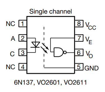
EDIT: Circuitry looks ok, I’d maybe use a lower resistor (datasheet recommends 330-4K, lower is faster edges but wastes more current) and connect VE to VCC just because I don’t like dangling inputs  but what you have there should work.
1 Like
I know i mentioned about sequencers before but im here to double down
ive got all the modules built but i dont know where to get my v/oct and gate signals from
like i want to test my envelope generator but dont have a trigger pulse from anywhere
got any plans for midi intergration? also wondering how other people are running their systems
1 Like
when i had my case ready and no sequencer i used one LFO to trigger the envelope followers and the other one for V/Oct. took a little fiddling around but was lots of fun.
@lookmumnocomputer do you plans to release an envelope follower module? something like the ms20 external signal processor would be nice!
also i am thinking about building this one:
not sure if it will work on 12V however…
1 Like
It probably works just fine; there’s nothing obvious in there that cannot be addressed with a bit of level tweaking with the knobs in the circuit, and 12 V is enough for the 7808 to work. You could perhaps adjust the voltage divider at IC 1-D but not sure that’s needed.
The choice of LM386 as an input amplifier is a bit interesting…
4 Likes


