here for future reference! hope that helps. however it seems that it doesn’t give a hoot the values of 13 and 39 as @Willi359 has had happy operation! very sorry. it was something that hadn’t been bought up till now. if it has im sorry for missing it.
5 Likes
perfect…
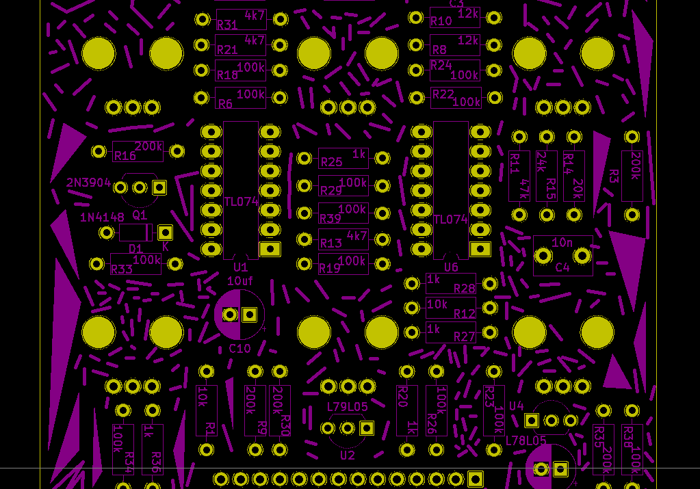
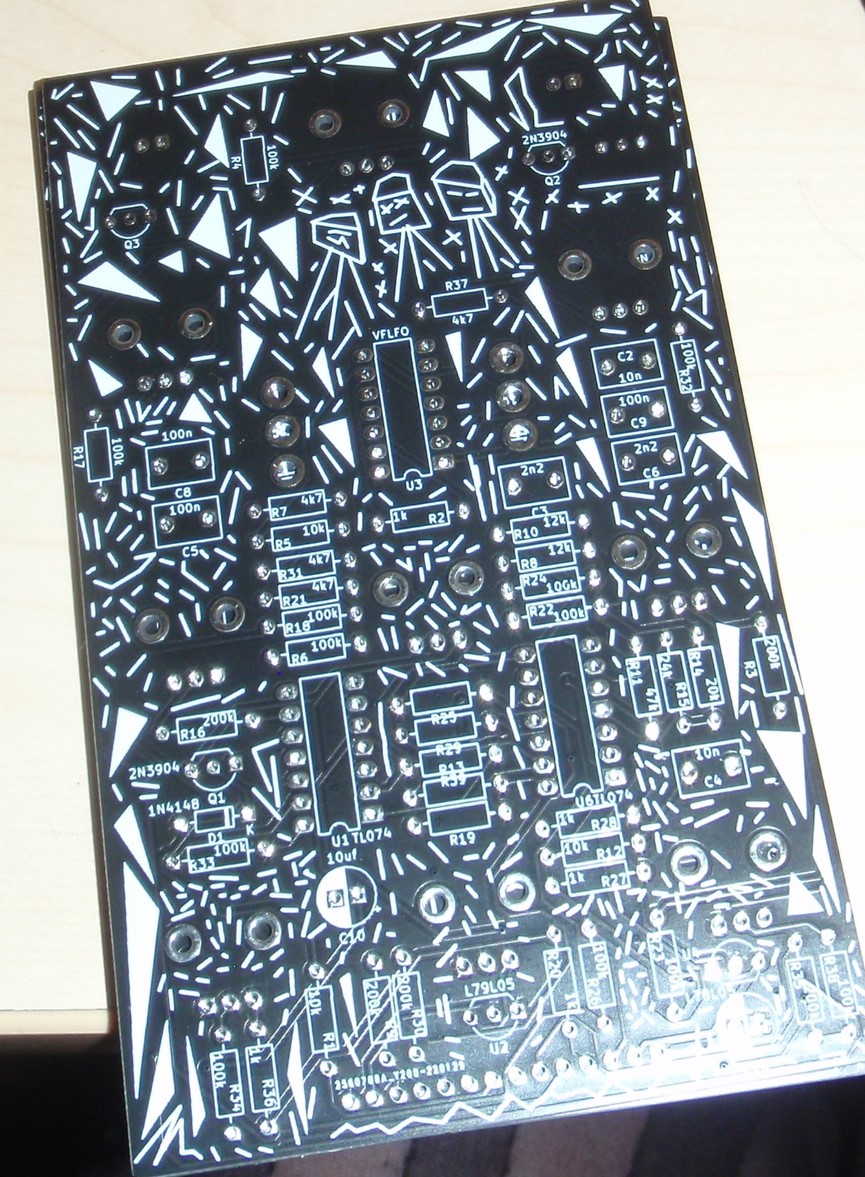
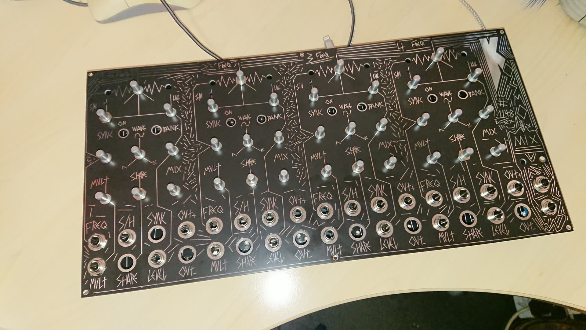
It would be good to have a page showing the PCB layout for all modules so that you can ID components for trouble shooting when the board is populated.
2 Likes
@Willi359 may be worth a swapping on them ![]()
2 Likes
I scanned all the PCBs before populating them for exactly this purpose…
Easy to do with google drive’s “Scan” feature on my phone.
3 Likes
yep! ok will add!cooolio.
2 Likes
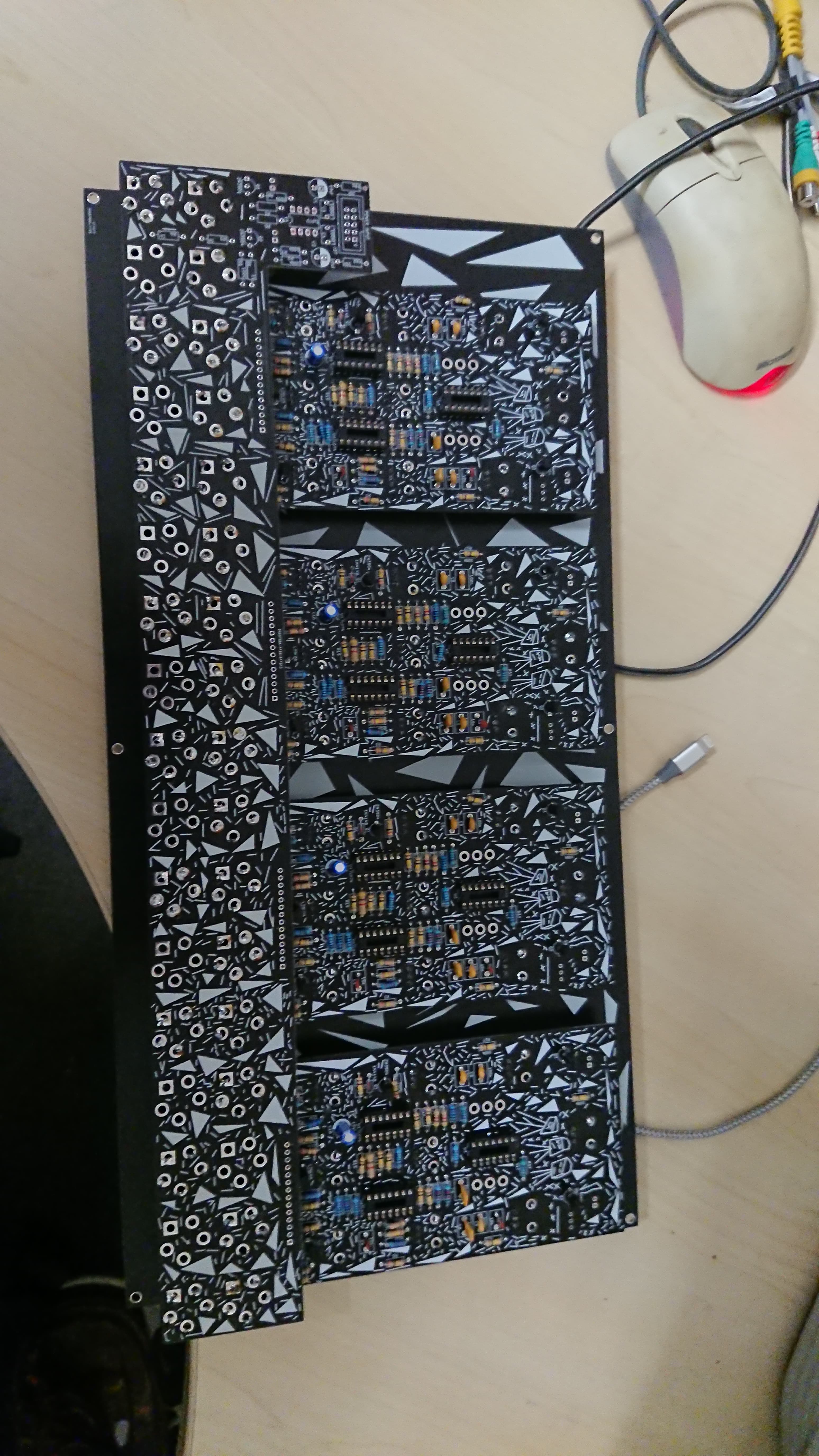
I am hitting this in a BATCH approach, populating each component type across all boards in one rather than building one board at a time.
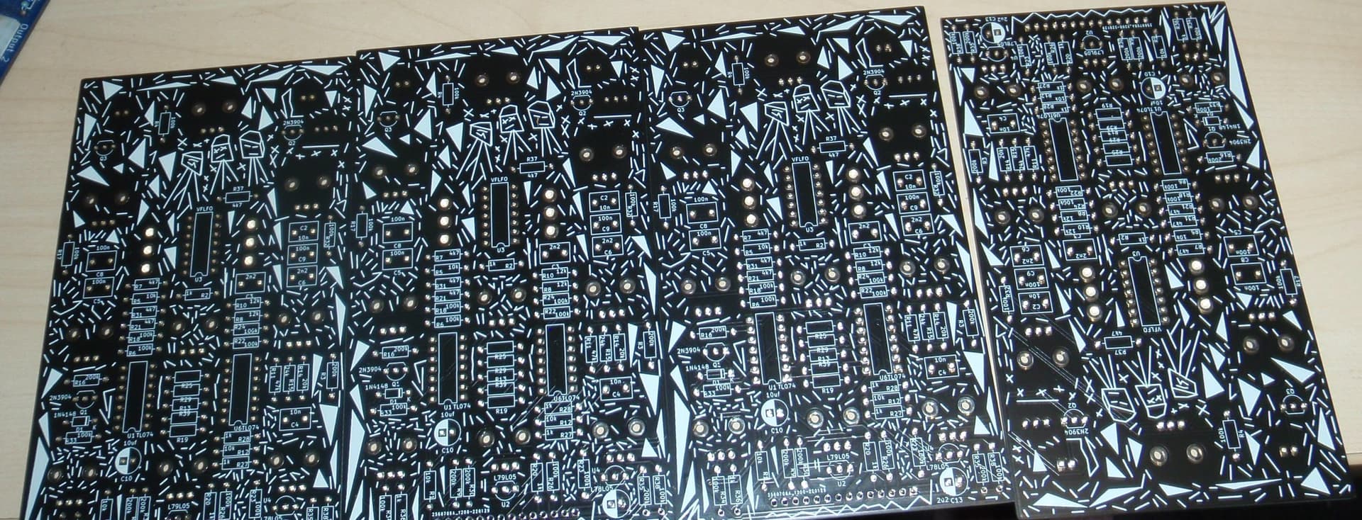
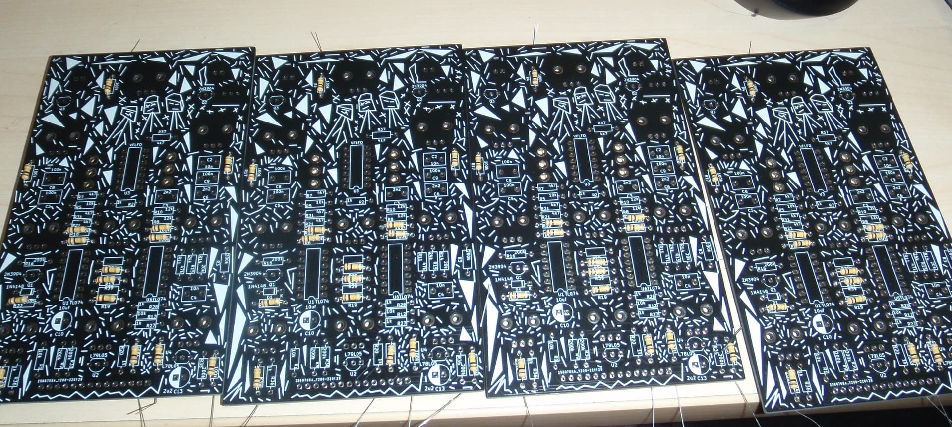
There’s more done, and over half the resistors are now in and soldered down. Just not picture of that yet. Ran out of matching 4k7’s I did use 4x .5w ones just to use them up.
Something was once mentioned, I think on the QUAD VCA , or another live stream “@sam do you orient all your resistors the same” or something to that effect. It never bothered me in the past but now I try to get all the same values the same way round… Not bothered which way, just all the same for each value. Pointless excepth fot the asthetics, which is pointless as you dont see it…
Rob
3 Likes
I made this same mistake. The LFO Range // Multiply was non-func
I just corrected it last night by swapping the 100K and 4.7k resistor positions
1k
100k
100k
4.7k
100k
is the correct placement
1 Like
those two resistors, 4.7k and 100k, need to be placed as per your reference pic or the Multiply will not function
1 Like
I could not make the time to fix my #1148 jet but i have it on my list. its case space got taken by other modules and i finished a #1145 single LFO so it got less urgent. i let you know when it is done… probably on a thuesday ![]()
1 Like
I thought that 4 LFO’s would be plenty but I was mistaken. 4 is a good start - I also have 2 more 1145’s to build.
1 Like
the change out took all of 10 minutes and I did not need to remove boards FWIW
1 Like
anybody know the function of the 100nf C8,C5,C9…
I can’t verify without the full schematic?
I ask because my box of 100’s all read 50nf… if they are just power rail decoupling then that shoudl be ok.
Cheers
Rob
Two 50nF make one 100nF, so doesn’t that help?
Almost there , ran out of box jacks and spdt switches. Out of pin socket too.
Though i was out of knobs so ordered 50 only to find the last lot of 50 i bought a while later.
1 Like
could have done, but ordered some better quality ones instead and they came out around 96.8.
1 Like
what do the two LED’s on the jack board do. Presently ( wityhout the LFO chips in ) one is on and one is off?
Cheers
Rob
i think it’s + & - output indicator leds
Ahh right, same as the individual ones but for the combined output. Makes sense.
Cheers
Rob
1 Like
well it turns out the batch buil approach gives consistent results 100% of the 4 LFO’s don’t O
@lookmumnocomputer any chance of posting up the actual schematic on this one? The single LFO has differences that make it hard to trouble shoot.
Cheers
Rob