Stick with the basic tools for changing function. Too many DAWs add prefix and suffix ‘handlers’ to basic MIDI so they dont get lost. It would be very easy to make a nano box with a din out to set them and leave the PC or keystep out of it.
1 Like
Evening all, hope you could help of where to start troubleshooting.
I built this module sometime before christmas and it was all working great, getting clock signals and I can verify that I was getting a gate out on channel 1.
Come to today, keystep pro arrived (wahey), plug everything up aaaaaand…no clock signal…no gates, all I get is a flashing status LED. Thought maybe it was something weird with the midi channels, nope, plug in my Crave in case the keystep is doing something weird, nope same issue.
Somehow between now and lunchtime (the last time I got a clock and gate out) somethings gone weird and I have absolutely no idea where to start trying to debug this! Any help would be greatly appreciated.
EDIT: should have mentioned that the midi thru works
1 Like
first id double check the jumper cable as when not connected the thru works and the status led flashes but it doesn’t go to the chip
Jumper cable appears to be doing it’s job, continuity test all clear when tested between the pads.
Not sure if this was a bad idea (probably was) I tried to test the continuity between the midi in (top connection) and pin 2 on the atmega and the gate/clock LEDs started to flash…
EDIT: Went to do the continuity test on midi in to pin 2 and it started working again…until I turned the tempo up on the crave. Also seems that only MIDI channel 1 is working
1 Like
Alright so an update, it’s busted again. I went through quite a few of the replies in this to see if there was anybody with similar issues. So I swapped out the two caps around the crystal. Discovered that the resistor on the test point was borked, so replaced that. And swapped out the cable from the midi in to the molex.
So far, no luck unfortunately. There was a period where if I did a continuity test between the midi in and pin 2 on the atmega, it would start to work, but only on midi channel 1. However I can’t replicate that anymore 
I’ve got a few more octocouplers coming in the post, but I don’t think that’s the issue as I don’t think the midi thru would work if that was the problem?
Tested power and reset pins on the atmega and they’re all at 5V, pin 2 gives me a reading of about 1.37V although without an oscilloscope there’s bugger all I can do about diagnosing that further.
Is there anything else I could try? I have an awful feeling it could be that the atmega is busted somehow, god knows how that could have happened or how I’d go about verifing that that’s the problem.
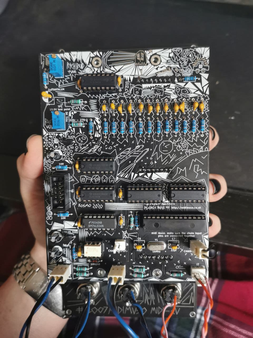
And as a final hail mary here’s some pictures of the back just in case a fresh pair of eyes can see if I’ve done something incredibly daft and I’ve just not spotted it!

1 Like
I got mine working by removing the two caps at the crystal completely 
3 Likes
Holy shit I think that worked!  Thank you very much!!! I think there’s a chance that I’m in mode 1A, which might only midi channel 1 working. Just need to figure out how I can change it with my keystep pro…there must be a way of doing it
2 Likes
If you have a usb2midi, you can try https://midimuso.co.uk/tools/
3 Likes
looks like possibly some of the parts ie: got slightly melted during soldering, maybe , I was looking close up at it
Hi I see that it’s sold out now ;_____;
Is there any chance it will still be available for purchase?
2 Likes
yep I was a bit busy this past month so wasn’t able to keep up with restocking things, I am in the middle of restocking things this week and putting up a new module. the midimuso should be back in stock by the end of the week, Monday the latest.
8 Likes
New module, eh? 
2 Likes
So… I just put together the MIDIMuso #1007, fairly simple build but i have a small issue OK big issue no CV !
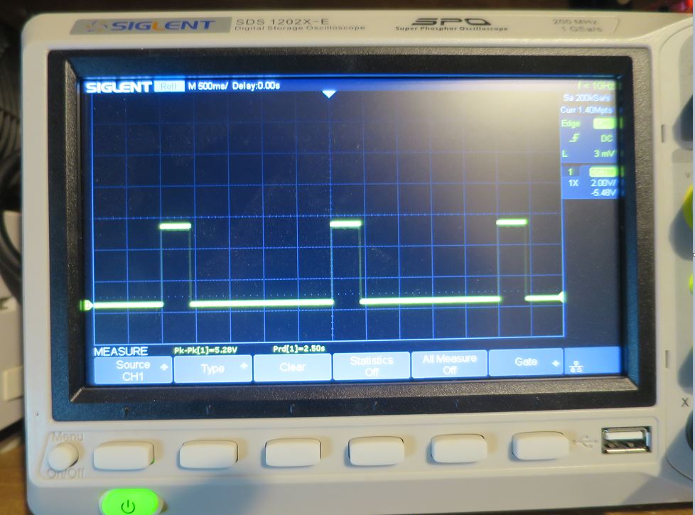
All outputs and LED’s are functioning correctly (testing with Siglent Oscilloscope (haven’t built my 3340 yet) but no voltage out of sockets B1,B2,B3 or B4.
Velocity 1-4 perfect
Pitch bend perfect
CC#1, CC#71, CC#74 perfect
clock out Perfect
Gates 1-4 perfect
things Ive tried / checked
removed the 2 caps from the crystal as per a couple of suggestion above.
Changed Midi cable (Both tested and working)
Changed midi source (Ableton via interface & Korg Electribe)
Sent each midi channel (1-12) to check
Changed the TL074’s with a batch from different vendor
Swapped the 2 CD4504s around - no change
checked voltage at CD4504 10v & 5V & GND
Checked midi info at Muso chip (dual trace oscilloscope) - perfect
Checked midi through - Perfect
So I traced CV1 back to pin 14 of the Muso but my scope is showing rubbish
My logic it cannot be the TL074 (U7 - CV 1-4 & Velocity 1-2 as velocity is a perfect signal)
it cannot be CD4504 (U4) as again Velocity works fine and when swapped the problem stayed the same.
I bought nearly all components from Rapid (as per Sams BOM) chips came from UK vendors & used a proper Tantalum 1uF (writing at front +ve right leg).
upon calibration I could not get the pitch bend to balance so changed R1 & R27 to 100K so calibration was spot on. And I used 220 Ohm for for R26.
The only chip I substituted was I used a CD40106 for the 74LS14 could that be it? (but then I’m getting midi through)
or is it because I’m testing it with no load - ie no impedance from an oscillator.
I know you can change the modes, but I actually want the mode that it comes with it as standard.
right taking a break from it now, I hope one of you might be able to offer some suggestions.
John

Gate
Pin 14 of Muso chip

1 Like
the only thing that comes to mind for me is the connects that is between thee 2 circuit boards for those jacks, as that’s the only real common thing, maybe track down which header socket they go through and se if any signal is going through it?
1 Like
Update
Thanks for the response Sam, I had already done a meter check from the tips to the opamps and got 100 ohms on each.
So I updated the chip off the Chrome app and its now working, so it must of been a ghost in the machine.

this is a loop of note C from C8 to C0 and the scope is saying 1.2V base to 9.4V peak so sound about right.
I’m not sure what the difference is between the LMNC default mode and 4MV from MidiMuso is but I’m just glad its not bricked.
Right next problem wife is due home in 20 minutes and I’ve done nothing all day but play with my toys

4 Likes
My go-to defense that never works: “I was learning a new skill sweetheart <3”
5 Likes
Hi swarm intelligence,
so after building 3vcos and some other modules it was finally time to get the MIDI-CV module working.
Everything went fine so far nothing unexpected happened… however until I wanted to calibrate the pitch bend with the trim pot.
I was able to calibrate the 10.6 volts on the “tuning” trimmer but when I started calibrating the pitch bend pot I noticed that the voltage im dialing in is not constant.
In other words the voltage (doesn’t matter where I turn it to) drops in 0.01Volt steps in about every 1-3 seconds and this keeps going even til it reaches negative territory. Since I got scared to blow something I stopped testing that at about -1.9 volts…
I checked all the solder points reflowed them when they looked sketchy but I’m a little lost now what could be the problem here… does anyone have a idea? <3 from Hamburg 
1 Like
cool! good job. maybe contact midimuso? regarding the differences it isn’t massive, there is return to bass however I think that he may have updated the normal code to include this mode, also the midimuso was A at 0 volts. the LMNC one is C at 0 volts. however this may have also been changed! off the top of my head I think thats the differences.
1 Like
hey morpheus im trying to figure out the problem you are having double check R1 solder R13 could be too. im not sure exactly what you are meaning by your description.so you adjust the pot and it only moves 0.01v every couple of seconds?? or the whole thing just heads downwards? is the power supply of the synth at temperature, there may be some fluctuation on this potentiometer as the power supply heats up
1 Like
Hi Sam wow you’re lightning fast 
Yeah what I mean is that I turn the trim pot to let’s say 0.5 Volts then stop doing anything and just watch the magic on my multimeter. And what happens there is that the voltage starts dropping as described by itself without me doing anything than watching 
In regards to the power supply you might actually have a point… when I started building the Microbus to power it I had some trouble with this transformer that was sorted after identifying my own stupidity in wiring it up wrong… however it could still be that there is a problem with it…