“Remember kids, the difference between science and screwing around is writing stuff down.”
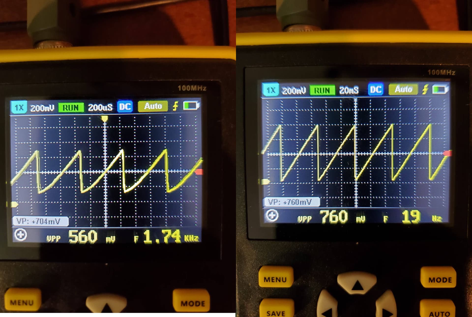
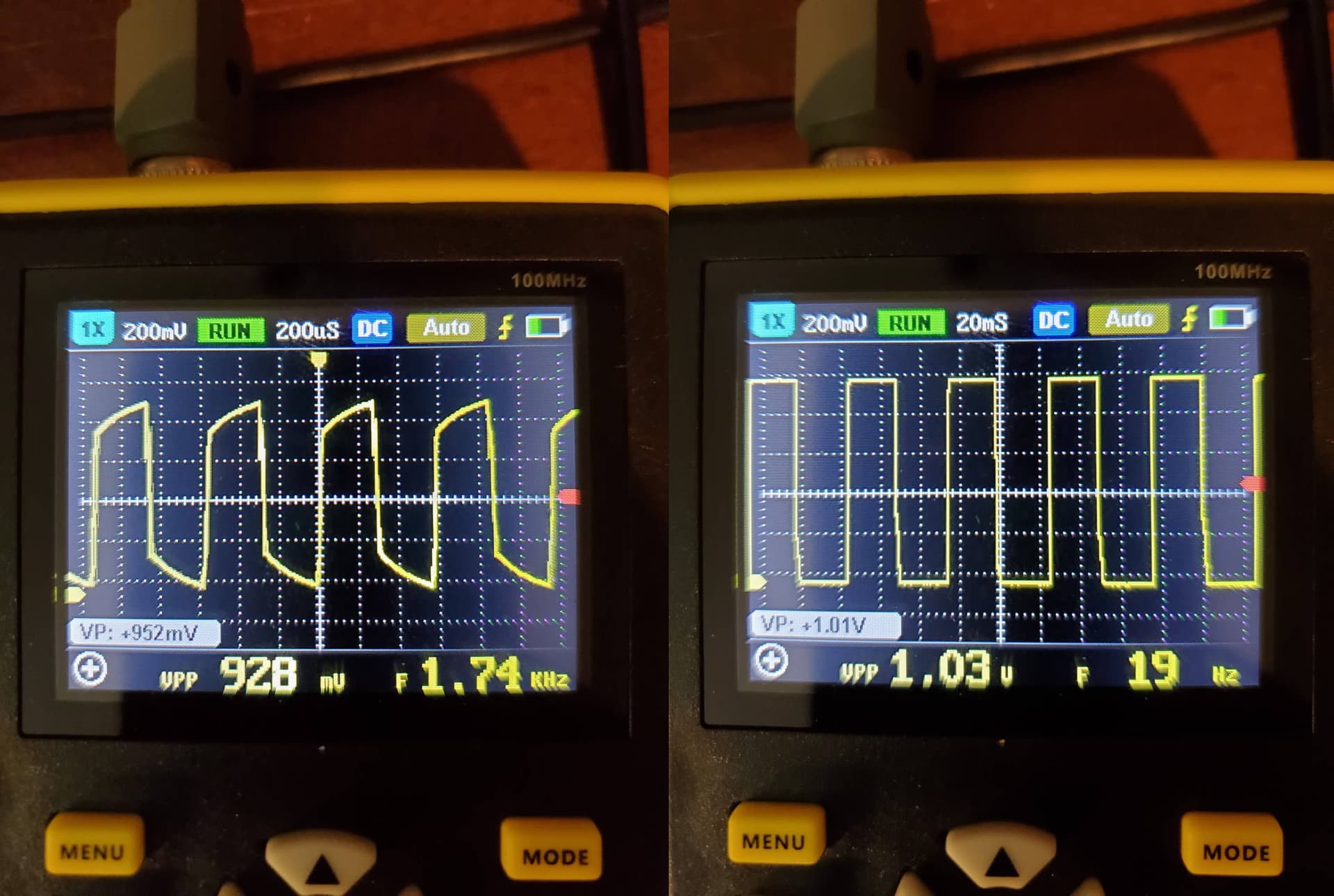
So here are some base line readings of my two VCOs. All of these readings were taken when the routemaster had things plugged into each of the other 11 power headers.
If I have a VCO running just by itself on my routemaster, it has a nice clean tone (to the ear). The moment I plug in the WAV trigger and the LFO to trigger it the tone gets noticeably more noisy and begins wavering in time with the LFO voltage swing & the triggering of the first wav bank.
So the ultimate question is this a PSU issue? Or does the stripboard VCO just fundamentally suck?
I am making progress but at the same time I am feeling a little disheartened with my modular in general.
I got the Euclidian rhythm generator working in tandem with my WAV trigger - and on the bright side, it is as much fun as I thought it would be. I’ll post more about the rhythm generator build later.
But… my VCO’s are still so dirty sounding that they are pretty much unusable. Without them my rig is about 90% useless. I went so far as to buy a 2A transformer to throw in, but after a little thinking and reading - the FC power supplies recommend a 1A. Before I destroy something I should probably explore alternate routes. I am a bit at a loss at this point, save for trying to build 1222 to see if it fairs any better. I’m still curious if anyone else has had the same trouble with the WAV trigger power draw.
Glad to hear you got it working, looking forward to that!
There’s been a thread here on these issues, I think the problem there turned out to be ceramic timing caps. Anything of that sort going on for you?
Overspeccing the transformer won’t damage anything. The transformer doesn’t ‘push’ power into the PSU, it gets drawn from it. If anything, you can run two PSUs from it…
I’ll have to do a bit of a deeper dive into these and poke around.
Also, I have yet to mod my routemaster with the extended ground - I’ll have to take the whole thing out again to get to the back side. I hard wired things in and am regretting it - I think the screw terminal barrel jacks might have been the way to go after all.
[edit] I just realised you wrote ‘dirty’ and I misread that as ‘drifting’. Afraid this ^ thread will be mostly useless to your case…
Yeah that’s what I went for, and in hindsight I’m happy I did. The routemaster has a MTA-156 footprint on the AC input, which has .156" lead spacing. Most screw terminals have a 5mm or 0.2" spacing. I was able to find some .15" screw terminals though. The holes in the PCB are large enough for these to fit.
Do you know how to change the input of the scope to AC coupling so that the trace is centred around 0v?
The reason you see a straight line is that the scope is ‘zoomed out’ vertically. On any scope, you should be able to adjust the vertical scale or volts per division(how many volts correspond to each box of the grid in the Y axis). If you change the v/div to say, 10mV, that should zoom in enough so you can see the PSU ripple.
Now this (the ac coupling mode) I am not as sure about. I flipped through as many modes as I could find (I don’t currently have it handy) and the only time I could see any activity with a PSU attached was when I zoomed all the way out - and even then it was just a miniscule and noisy looking line. The manual was not particularly enlightening.
Now I see the vertical sensitivity is 50mV/div. That’s a bit high for viewing the supply ripple. At least, I hope for you lol.
Try setting it to AC coupling, the smallest vertical resolution and a horizontal timebase of around 5ms/div. That’s your best chance of seeing anything
The video linked shows how to put the unit in AC / DC coupled mode and demonstrates the onscreen indicator to confirm you are in AC mode. This is shown at 4:15
When you are in AC mode, and you connect the probe to a powerline I would expect to see a flatish line centered on 0v, if you are still seeing a line at + or -12v you are still in DC mode, try pressing the white AC/DC button once more.
Once you see a signal centered on 0v ish then you could use @TimMJN suggested settings.
I just put in my new transformer (dont mind the fact that it is dangerously close to everything at the moment) and adjusted my voltages on the routemaster pots.
Sorry for the high frequency buzz, but the noise is more noticeable this way.
Having just hooked up my voltmeter - there is a .01v drop when I plug in my WAV trigger.
Is this because the WAV trigger is just too much? Or is my VCO too sensitive? Perhaps a combination of the two?
So the settings across the top are:
1x 10v RUN 5mS AC Auto
When I put the probe on either the +12 or -12, it jumps to 8 or 9 and then drifts back to 0 again.
Yes that’s good! The ac coupling removes any dc components in the signal you’re measuring. So the allows you to zoom in on the fluctuations without having to deal with that large 12v offset.
Managed to get some magic smoke from my glide because I am still bad at making power cables but everything else works a treat. Spent a few seconds jamming this morning before running out of patch cables.
To do: Small fixes #3 Filter input plug is soldered to the sleeve or something.
Quantizer CV2 pot unresponsive.
Big question marks
Mult still needs a lot of love - still cross talk between banks & the meters need hooking up.
Have not plugged in the safety valve, but I imagine the noise issue has not gone away. I do have a big 1/2 watt resistor to swap out though.
To Build:
Cable tester!
Turing Machine
Branches
Case #2 (!)
I’m still getting noise in my two oscillators, but I’ve pretty much accepted the fact that they are never going to sound perfect.
It works great. My homemade cables have been very reliable (using connectors and cable from Tayda and this tool) but if there is a problem this will catch it before the chips do.


")
