Ok, didn’t get to melting ANY solder last night 
Instead I decided to work on solving a knob problem. Going back to my first 2nd post and my quest to 3d print aesthetically pleasing custom knobs. Printing knobs that fit knurled or D-shaft shafts is easy…I have no problems with either of those. The problem has been coming up with something that works on smooth shafts since adding a set-screw doesn’t really work well as they tend to just strip out.
I had mentioned the possiblity of pursuing a 2 part solution. And that’s what I finally decided to try last night. An inner soft housing printed in Siraya tenacious flexible resin, with a hard outer knob printed in standard resin.
And it seems like it may work.
First I tried just printing my original design in 100% tenacious. (I also tried dying the finished print with analine dyes to see how that would work…it…didn’t work great.)
This wasn’t very successful. The thin inner part that grips the shaft was TOO flexible. So the parts with the cutouts did nothing and the solid part deeper in wasn’t quite tight enough.
So - dual material it would be. My first attempt was similar to the commercial knobs I’ve been using that came with some cheap amazon pot’s - just an innner circle slightly smaller than 6mm (5.9 to be precise) with 4 “arms” coming off to the outer shell. I printed a few up and tried them. And at first they seemed to have promise - but after about 30-40 seconds they loosened up and didn’t grip the shafts well enough anymore.
So back to the drawing board. I made the center a bit smaller (5.7mm) and added twice as many arms. Also tweaked the depth of the arms a bit to make the fully supported top a bit deeper:


I printed a few of those…
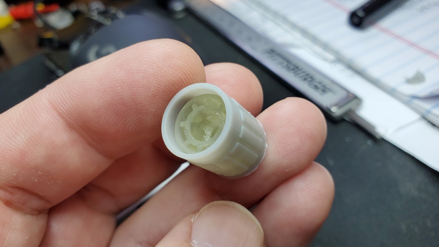
And hey this has promise! They were a snug fit, and stayed snug. Even this morning they were still tight enough to turn the knobs - if I really torque them at the ends of their movement they can rotate on the shaft - but they still grip well enough to move my smooth shaft pots and these are fairly stiff pots so I’m happy.
Next time to model up a hard shell to go over the inserts:
My idea is that the shell should compress the soft inner part a bit to give an even tighter grip. So I left no clearance between them. (the top of the insert is chamfered partly to make it easier to put the cap on but also partly to compensate for “elephants foot” from printing.) I just drew up a quick and dirty design very similar to the commercial knobs. Then printed a few of them off in basic grey resin (since I have lots of it…I’m almost out of my nice black resin.) I printed half of them with the top on the build plate, and half with the bottom on the build plate. Both had issues…but work.
The ones printed with the top against the build plate had pretty bad elephants foot and the indicator mark was lost. The ones printed with the bottom against the build plate the mark was visible…but the bottom had bad elephants foot - and on one of them part of the bottom blew out due to resin getting caught inside while printing. Printing these angled is probably the best bet…but will cause it’s own issues. Further experimentation required.
But they have the nice tight fit I was hoping for:
The hard shell also seems to make them fit snugger like I was hoping - with the shells on these are really hard to pull off and it takes even more torque to get them to slip even on the smooth shafts.
They’re not what I want aesthetically yet…but they’re functional and a step forward:
You can see that top knob has no indicator and gnarly elephants foot. And on the two printed the other way they both have a small dimple in them which again is due to the forces of the resin while printing. So i’m going to have to try another batch printed at an angle with supports to see how that goes.
As for cost/time…
The inserts I can print 15 at once it looks like. Due to how resin printing works printing 15 or 1 takes the same amount of time which is just under an hour and a half. The tenacious resin is pretty expensive $65 for a kg (or about 1l) even so 15 of them only use about $0.88 worth of resin according to my slicer which works out to just under $0.06 per insert.
The caps I’m still experimenting with the best way to print. Without support they take about 1:15 minutes to print up to 10. But as my first test shows that gives less than optimal results.
With supports I can only fit about 6 at once and they time goes up to an hour and 45 minutes…cost is negligible. The standard resin I use is $30 per kg (which is also about 1l) and my slicer is reporting that it’s about $0.17 worth of resin to print 4 with supports. Or about 4.25 cents per cap.
So while details on the caps is still pending it looks like about $0.10 per knob with this method and about 5 hours time on the printers to make 15 knobs. Since I have two printers I can do inserts and caps at the same time so my time is closer to 3:30 to do 15 running the printers in parallel. The caps are the slow part though and since I’m still experimenting with them that could change. If I could get them printing well without supports it would really speed things up…but I can’t think of a way to do that without adding a hole at the base somewhere.


 I’ve been trying to learn guitar off and on for almost 40 years - admittedly mostly off until the last 10 years when I’ve tried to get more serious about it.
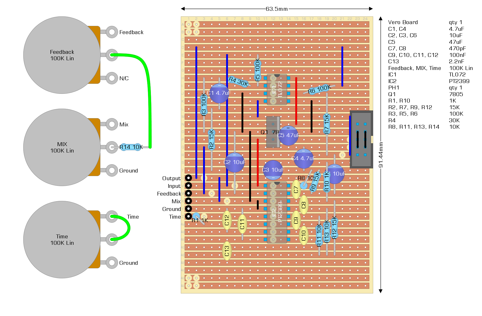
 ) I made a few minor tweaks to the stripboard layout to add an eurorack power connector and bring all the connections to 6 adjacent pins so I can use a JST-XH connector to attach the panel: