My first DIY modules - starting a Kosmo format build

Yeah, I’m rather confident they’ll make it right. Just a bummer to have it happen on a Friday which due to the time zone difference means even though I got the empty package in the morning it’s 7PM for them so they are unlikely to even see my message until Monday at the earliest.

But - USPS came through with a few other things I had ordered including some AS3340’s and AS3360’s which were the last bits I needed for a couple of other modules (some of those are earmarked for the PCB’s that didn’t show up…but others were just spares for other ideas.)

Also got a pack of 2pin header housings that I didn’t remember ordering (I just ordered more yesterday!) so that was a nice surprise :smiley:

3 Likes

that happened to me I think it was https://synthcube.com had sent me some pcbs . when I got it the package was empty , they did replace but what an unnecessary hassle . those edges are sharp and need to be rapped before going into the cardboard shipping sleeve especially with multiple boards .

1 Like

So my subject line is going to become increasingly inaccurate but I don’t want to clutter things up with a new thread for each module. This is really more of a build log than just my first synth.

Last night I decided a LFO would be nice to have next since I have to keep going to my neutron for one testing things. Debated a few simple LFO options I could build and decided to try the “Simple LFO 1.4” from David Halliant seemed like a good design and MIAW’s build indeed looked simple. But I don’t like working straight from a schematic to solder…so started drawing up a stripboard version first. And…quickly decided that my stripboard routing abilities were not quite there yet!.

So Instead thought it would be better to find an LFO with an existing stripboard layout. And what was in the first post in the verified stripboard layouts thread? A "Roland System 100 LFO’ a dual no less…and verified as working by @Doolang who’s noise drum layout work well for me on my last module. Sure!

For practice I decided to redraw it first. Considered converting it to use a single TL074 instead of two TL072’s but I have a bunch of TL072’s on hand…and also decided a dual wouldn’t quite fit in a 20mm wide module. Especially if I added the shape pot a variant posted later added. I also found the labeling somewhat confusing and in my late night stupor wasn’t able to figure out just how it was meant to be wired to pots/jacks/switches…But found this layout of the same circuit as a single which was labled a bit more clearly:

Or at least…was a bit more clear to my late night brain. But as I started to redraw it…I quickly decided it made way less efficient use of stripboard than I wanted for a quick and dirty LFO. So…I took a bit of inspiration from both and redrew it to fit on a scrap of stripboard left over from my last two modules:

Yeah…my jumpers are a bit uglier…but it fit in the thin strip of board I had. I also added some caps on the power rails since I was surprised to see there weren’t any.

Soldered it up then drew up a panel and set it printing while I worked on a little home improvement project. I’m starting to get my process for drawing panels in Fusion360 down pretty smooth. If there’s interest (and it sounds like there may be) I may try recording the process next time.

I didn’t bother with adding pin headers this time…I wish I had since the wiring is a mess now…but…I just didn’t see a good way to make them fit on the small scrap of board I was working with.

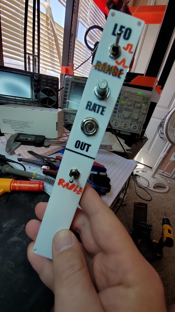
Hooked it up to my oscilloscope first…and…it works…but it’s not exactly a LOW frequency oscillator. The lowest frequency I was getting out of it was about 40hz. And using the range switch it sometimes freaks out and stops oscillating all together. I tried removing the electrolytic caps I put on the power rails just in case somehow that could be causing a problem (though I couldn’t think of why it would) but sure enough it’s still acting the same.

Oh - I also messed up and forgot to include the Waveform switch on my panel ( I decided to go with a switch rather than two jacks…but may change it to two jacks) and wired what I had labled as range to the waveforms. So had to make some sharpie and drill mods to the panel.

Here’s a little video of where it’s at.

In the video you’ll also notice that the snare side of my noise drum has developed a fault as well…both the snare and hi-hat were working…but now suddenly the delay knob on the snare isn’t working. Not sure why yet. Tried swapping the pots and it acts the same so it’s not a bad pot or wiring on the pot is all I’ve determined so far. Will have to take a closer look tonight.

Not sure if I mangled something in my re-draw…or in my assembly…or what yet. Will have to take a closer look a little later this evening.

Right now I’m about to get shade over my work area outside. (it’s apparently 118f out right now and lacking a shop all my woodworking gets done outside) So going to take my kid out for frozen yogurt then hope it cools down a bit and I get more shade so I can cut a few boards and toss together a case.

Oh - I also tossed together a little power buss so I could hook up more than one module finally…and made some more power cables with the red stripe on the correct side:

This should tide me over for a few days…I ordered one of @analogoutput’s boards off his Tindie this morning to go in the case :wink:

And speaking of Analogoutput’s projects…I did get another package yesterday that wasn’t empty:

I knew I wanted a quantizer…and liked the idea of the DAC/INO board for experimenting so when I saw his post I more or less immediately ordered a few boards from JLCPCB. I only need one faceplate since I only plan on building on quantizer…so will make the other 4 available soon. JLC shipped so quick I didn’t even have time to order a few parts I don’t have on hand for these though so it will be a bit before I get it built up and put the extras up. The DAC boards…I kind of want to keep one or two more for experiments though so I I’ll have more faceplates to get rid of than I will full sets.

But overall I’m starting to like the way my 3D printed simple modules are looking - can’t wait to get a case built this evening and try mounting them up…hopefully that will also help stop things like the snare suddenly deciding to stop working right :smiley:


If anyone has any thoughts on what I should look for on the LFO or Snare when I get to debugging them this evening I’d love to hear it!

7 Likes

Call it a log, journal or odyssey even just keep it coming. Enjoying your progress and results. As I have mentioned to others, your record of work is as important a product as your synth. Cheers.

4 Likes

Ah, found the mistake on the LFO.

Missed a trace cut hiding under C1. So C2 was accidentally tied to ground and one of the the non-inverting inputs as well as the switch.

Quick twiddle with the drill bit…and…I’ve got nice low frequency pulses now :smiley:

Not quite as low as I was expecting…seems like 1hz (by ear…I haven’t put the scope on it) is about the slowest. But both ranges work and I can get slow enough pulses to make some drum hits.

Now decision time…what to build up next. Still a bit too hot out to build a case (it actually went up a bit to 119F now) A VCA would be nice…I wasn’t going to stripboard one since I that’s one of the LMNC modules I was expecting yesterday. Same with an ADSR and VCLFO. Maybe I’ll step up and try a filter next. Should probably figure out what happened to the drum before I move on.

5 Likes

I pluralised the word “module” in the topic. Keep going, you write clearly and your work is interesting.

Thank you.

3 Likes

Ahhh, love the simple solutions. I’m better at the needlessly complex ones myself unfortunately :smiley:

Thanks for the tweak and the compliment both!

Here’s a quick vid proving the fix…and showing how LED’s look when mounted to shine through the panel. They show up through the white pretty well…but don’t diffuse much and the black of the text blocks them really effectively. So…putting it right behind a word doesn’t work out the best - I’ll have to think a bit more about where I really want them positioned:

5 Likes

Let me know where you live so I can not go there.

2 Likes

Just check my tindie order :smiley:

We actually hit a record here today. 120F previous high was 115 recorded back in the 40’s. It’s also the first time two days of 120F have been recorded in Sept. in Yuma, AZ. So…yeah…gnarly day for sure!

But…I went out just before sunset and ripped up the sheet of ply I found in my shed. It was a pretty ratty piece with some serious water damage on one edge and the others looking well worn and the whole thing a bit warped and twisted. But I was able to find enough good bits for at least one “Kosmo Standard” case made to Sam’s dimensions. I also had a sheet of 1/4" HDF that made a nice back, quick pass with a flush trim bit on the router and it almost looks like I put some effort into it :laughing:
No photos because I brought it in and tossed a coat of paint on it, and the light where it’s sitting to dry isn’t very good. Also…I haven’t dug out any pine strips yet for mounting rails. Not sure if I have any on hand. Need a few other things from the hardware store for other projects anyway so not a big deal.

The other projects kind of help, that’s why I had spare paint on hand. My daughter picked new colors to paint our hallway, her bedroom, my bedroom, and our bathroom so I’ve been doing a ton of painting lately. The bathroom was a bear - so much trim. And the walls were in terrible condition so I had to sand them down first. And the door…oh the door. This house was built in 1963 or 64. I counted at least 7 layers of paint on the door. It was almost 2mm thick in some places. I couldn’t put another coat on because the door was having problems closing properly already. And it’s an unusual size door (and solid wood) with non-standard hardware…so replacing it would be an even bigger pain. I’ve spent most of the past two weekends in a respirator with a heat gun and sander getting that thing down to bare wood. I actually weighed the paint removed from one panel on it and it was almost 2lbs of paint! Based on that the whole door must have had almost 12lbs total. It’s insane. Just one little section done so tomorrow I should finally be able to paint it and finish the bathroom.

But…I’m WAY off track.

The Synth. I fixed the snare! What a dumb mistake. I had swapped the wires for the delay pot and the output jack somehow. It’s an impressive mistake since I used a 3 socket on one and 2 pin on the other so I wouldn’t get them mixed up. So…really not sure how I managed that. What really threw me off was that it still mostly worked and sounded almost the same. Did NOT expect that.

But - wired up correctly the snare definitely sounds better and the difference between the snare and hi-hat is much more noticeable.

Also with the LFO now actually running at low frequencies I hooked up the oscilloscope to see just what it was giving me. Looks like the low range is giving me 1.74hz to 12.5hz and the high range is giving me 40hz to 257hz. So…the high range still isn’t really low in my book. I may try swapping some other values on C2 and see if I can’t find something I’m happier with. Keep both ranges low and see if I can’t get some really low frequencies out of there. I still have some space on the board too…so may play around with some other ideas.

3 Likes

It looks like the board is bleeding after having been cut with a knife. Not only that, it has been shot at several times as well! Is this how you treat all your electronics?

2 Likes

The “Roland System 100m LFO” claim is a lie, of course. This is way too simple to be that. Actual Roland 100m schematics are here.

Presumably the actual Roland LFO doesn’t have two limited ranges with a great gaping hole (12.5 to 40 Hz) in between. But to me it’s not that the upper range is too high. Indeed it can be very useful to have an LFO that goes into the lower audio range. It’s that you’re only getting a factor of 6 within each range. For comparison the Moog Mother-32’s LFO runs from 0.1 to 350 Hz without a range switch — presumably with an audio pot. The two ranges here differ by a factor of 22 (C1:C2) so you’d better have a larger factor within each range than that. It’s way too early in the morning (5 am, bad dream and full bladder) for me to be trying to figure out this circuit (seriously, stripboard layouts are not schematics, don’t build without a schematic) but I’m seeing the pot here connected to 10k and 15k resistors one or the other of which I’d guess is limiting the high end.

2 Likes

Yeah, I found the actual Roland schematics while trying to find a schematic for this circuit before I built it. Also drew one out before starting - but trying to unwind a stripboard layout wasn’t as much fun as just building it and seeing if it worked. So few parts and fit just right on the scrap of board I had so why not. I tried to find an original schematic for this design or even an original source to see if I could figure out why someone called it that. But had no luck. I did just find one now searching again and it looks like it’s probably correct: https://imgur.com/a/SjuDHjW

Side note - DIYLC both impresses and frustrates me. It’s nice that it can generate a net list and it is defintiely easy to draw a layout with it. And the “highlight connected areas” feature help a lot with tracing things out. That’s a big part of why I’ve redrawn the circuits I’ve built - so I can use that to confirm the connections before and after building. But…I really wish it worked more like a traditional EDA tool where I could draw a schematic, generate a rats nest and then route it on the strip board. I’ve yet to find any tool that can do that. I did find a few workarounds to do it with Kicad…but they had some pretty major compromises.

I hadn’t even stopped to think about the range. My Neutron is claimed to be 0.01 Hz to 10 kHz - I’ve never measured it to confirm. But I do like how crazy low it can go (and the smooth transition/blending between waveforms is fun as well. (Kassutronics has a schematic for his own variable waveshape LFO I considered…but I don’t think I have a suitable jfet on hand for the triangle to sine conversion: https://kassu2000.blogspot.com/2015/10/variable-waveshape-lfo.html) I just checked it with my scope and yeah…that is pretty much the range (it doesn’t quite hi 10khz at the top but 9.8somthing is close enough.) I see the specs on the actual Roland system 100 schematics that the range on their LFO is 0.05hz - 30hz. Not as impressive as the range of the Mother-32 or Neutron’s LFO’s…but still much better than this “clone” circuit’s offering.

So thanks for tweaking my thinking. I hadn’t even considered the limitation of the range - only it’s extents. A fresh perspective always helps.

Either way though…I think I’d rather put effort into building a better LFO than improving this minimalist circuit. It serves me immediate needs of giving me a source of low frequency waveforms - even if it isn’t quite as flexible as I’d like.

At the same time…I’m tempted to break out the breadboard and play around with it as a starting point due to it’s simplicity. Swap to a TL074 to get a few more op-amps…and boost the triangle a bit…and a sine converter (if I can dig up a suitable jfet from my parts bin) see if I can’t tweak the range…I could have a fun afternoon or two just messing around with it.

But right now I’d rather focus on getting a few proven designs built to get a more complete system to play with before I loose myself in the weeds of tweaking circuits :wink:

Also…realized that despite measuring multiple times building my case I still managed to mess up in my rush to finish before dark last night. Somehow I wound up 2mm short on my sides. Grrr. I swear I measured them before and after cutting and they were 400mm but now that it’s assembled they only measure out at 398mm. So…I either have to find a way to sneak 2 more mm into the case…shave down any modules I put into it…cut it down to 1 row…or only populate 1 row and use the rest of the space for storage. This is why I don’t usually paint projects until they’re proven…I swear paint curses things and just causes problems. I can’t explain the physics of it but I’ll swear that the paint made those sides shrink :laughing:

Oh well, I have enough wood to build another. And it will be a bit before I have enough modules to even need two rows. So not the end of the world.

2 Likes

haha yeah right .
just don’t take those plastic face plates outdoors they will melt for sure . looks great so far and glad to here you are getting the bugs worked out , thats always a nice feeling .

3 Likes

I’ve actually done a number of experiments on this over the years with various materials. One nice thing about the photo cured resin prints - they don’t mind heat. But they’re small, hard to get accurate dimensions in all axes, and are usually brittle.

The standard FDM materials though…yeah they don’t like my weather here. But when I printed my MPCNC machine I knew it would have to live out in my shop and I didn’t want to leave the AC on out there all summer so I did some tests and put a few failed prints in my truck to see how they’d hold up.

What I found is that as expected PLA does get soft fast…but - it won’t usually deform under it’s own weight even when inside a truck parked in the full sun for 6 hours on a 115f day. If you touch it though…it’s like silly putty. What was more interesting was that after a month of being in the truck…they appeared to anneal and no longer got soft enough to deform without a lot of pressure or extreme heat. You won’t hold sub-millimeter accuracy going through that kind of heat treating…but it is a trick worth knowing about.

PETG handles the heat better. Those prints in my truck took a lot of effort to deform on the hottest days. Same for ABS (though I don’t like printing ABS due to the stink.) Nylon - really tough to print and crazy expensive…but…takes even desert heat just fine - and you can dye it with analine dyes to get almost any color you want. Worth the effort for some things.

For these modules…I don’t plan on them leaving the house. At least not in summer. I won’t rule out the possibility of the system coming camping to a few musically inclined camp trips we do every winter. But that time of year heat isn’t an issue. I’ll be more worried about sand getting into things, condensation, and plastic getting brittle in the cold desert night :smiley:

Also - While working on my painting project today I realized I can fix the issue with my case. It’s only 2mm off. And it only has to be right for the first few inches of the box. I can just plane and sand 1mm off the inside top/bottom and will have room. Will probably be the quickest way to solve the issue.

2 Likes

was just kidding / commenting on the heat down there . yeah its kinda hard to accommodate for environmental conditions when dealing with making delicate electronics portable , unless of course you have a military budget .

1 Like

Well, let’s see if I can fill up those rows quicker with some modules that need a bit more real estate. Based on the parts I have on hand and how complex of a circuit I felt like tackling I decided to try a MS-20 LPF next since it seemed to be one of the simplest filters and I had all the bits on hand.

I went partly off of LMNK’s stripboard layout comparing it back to Rene’s schematic to draw up my own stripboard since I wanted to fit in a 10pin power plug, I wanted to have all my I/O on connectors, and most of all because Sam’s layout was wider than the stripboard I can find. (Seriously where do people find those big wide stripboards. I’ve seen a couple of long power boards made out of stripboard but I can’t find any wider than the “large” boards from Tayda. I ordered some off of Amazon - but what I got was not what was pictured and wasn’t strip board it was just proto board with individual pads. And while I can use it for some things I’d rather not use it for too much because I’m not big on making that many solder jumpers.)

Anyway - I came up with:

I could have made it a bit narrower…but I wanted to leave the board full width so I wouldn’t have to drill a new mounting hole. I didn’t redraw the wiring for the jacks/pots - mostly because I’m lazy.

Started soldering it up yesterday and finished tonight after dinner:

(Yes, there’s a glaring error in my wiring if you look for it, and an error caused by my layout.)

The panel printed overnight. Not sure I labeled things very accurately though…like why I went for Freq for Resonance. It was my second time too…the first time I had the spacing for the board mounts wrong and managed to label both pots RESO without noticing.

And a solder shot for those who enjoy that kind of thing.

I still need to trim off the unused bits of board.

Plugged it in, fed the output of my simple VCO to it and…I could hear a tone. But neither knob did anything. Hmmm. Oh…I forgot to wire the output jack to the resonance pot. Whoops!

The other error? I forgot to leave space on the connection for +/- 12v to the Cutoff pot. I also included a ground I would up not using since I just chained all my pot/jack grounds off of the ground I ran from the input connection.

So…let’s just run that missing connection in there:

And hey it works…ish. Every now and then it just suddenly goes dead. Unplugging power and re-plugging it gets it going again. I did use a 10k pot instead of 4.7k since I didn’t have a 4.7k or even a 5k on hand. And looking at it now I realized I used the 10k pot for resonance and the 100k pot for cutoff. So…I’ll get those swapped back which will probably help some. I see Rene used a log pot for resonance though and 47k not 4.7k for his CV and Cutoff pots.

I can see swapping log for linear depending on the response curve you like. But 4.7k vs. 47k seems a bit of a big difference there on the other pots. I may try some 50k’s in there (since I don’t have 47k on hand either) and see how it goes.

I’m also not sure the blue LED’s are a good call here since they’re part of the feedback loop and probably have significantly different forward voltage than the green Rene used and red Sam uses.

I’m also a bit limited on my testing because my power board is only wired up with 2 outputs right now. I have potential for a third but need to make a few more solder connections. Just being lazy since I ordered one of AO’s power strips and since it shipped today kind of want to wait for it and do it right instead.

Also - “fixed” my case a bit yesterday:

Used a top bearing flush trim bit guided by a scrap of pine stuck on with some carpet tape to shave a few mm off the inside. I won’t be able to shove things as deep inside as some cases…but it will be good enough. (The blue was just because I’ve been painting the trim in my hallway that color - but now that I think about it will go kind of nice with the white panels and blue led’s I’ve been using.

I need to mount the moutning cross bars tonight and get some modules in there. Also - those little feet I 3D printed out of Sirya Tenacious resin which is a flexible resin - so unlike most resin prints they’re not at all brittle. I have some PLA feet on the box right now but wanted something a bit more resiliant. Yeah…I could have bought feet…but…would rather save a trip to the store :smiley:

Well, we’ll see what I find when I make a few tweaks after getting my daughter in bed tonight. And need to start work on a VCA next I think.

4 Likes

They’re voltage dividers, so for the filter the actual resistance matters relatively little as long as it’s not too large compared to the impedance of what they’re connected to, which is something higher than 100k (the series resistor they connect to). But (on the CV inputs) they also dominate the input impedance of the module, and typically that’s in the ballpark of 100k. So 47k is a factor of two under that, while 4.7 is a factor of 20. A 100k pot would be about equal to the resistance after the voltage divider, not awful but a little high. So 47k (or 50k, let’s get real, it’s the 21st century and no one has 47k pots) seems a good choice. I would certainly not use 4.7k (or 5k) if I were doing it.

But again, none of that should significantly affect the performance of the filter.

The resonance pot goes into an op amp input so I wouldn’t expect it to be critical at all.

5 Likes

See, I hadn’t thought it through fully yet. I gathered they were variable voltage dividers - just hadn’t though enough about the actual numbers to think about the details.

I’m a bit odd with numbers. I tend to have good intuition for math - but am terrible at arithmetic. I can grasp complex number theory concepts and usually have a fairly accurate gut feeling for the value of an equation. But I can’t add 2 and 2 and get 4 every time. I’m a bit better with a calculator…but even then I transpose numbers and loose track of decimals. Just the way my brain is wired it likes theory but is bad at practice.

I did swap the the resonance for a 100k log pot like the original schematic called for and put the 10k linear on the cutoff. And at first it seemed good. But then suddenly it cut out again and every time I’d cut power and re-apply it would freak out even quicker. So…I’ve still got something off.

I did go ahead and do some mechanical work on the case:

Few notes on that. It feels very wrong with the VCO down in the lower right…but…there is some method to my madness. That side of the case is closer to my desk - and I’m putting working modules on the bottom and those I’m working on on top since it’s easier to reach the top from my desk. Eventually I’ll re-arrange - this is basically just what works for me right now even if it feels kind of upside down and backwards.

I also left the gap next to the modules on purpose because it was just too hard to grab and twiddle the VCO knob if it was right up against the side. I’m thinking about redoing the face plates for those a little wider. I’m just torn. They’re 25mm right now (one Kosmo unit) making them 50mm wide feels wasteful…but making them an odd multiple feels aesthetically wrong to me as well. I’ll just play around with my layouts a bit and see how it goes. That’s one thing I’m still terrible at in CAD - visualizing dimensions in the real world. Almost everything I design winds up way bigger or smaller than I think it’s going to be (my brain and numbers again.)

Speaking of my 3D printed panels…the 1.5mm thick PCB mounts I’ve been using are ok on the smaller boards…but for the Filter they’re proving too weak. So I need to beef those up a bit as they’re starting to flex and break already. I also modified the “flanges” where they mount to the case - my original ones only had 6mm from the top/.bottom edge to where I started the reinforcing rib. But that cuts it a bit close on getting them installed in the case. The LPF I used 12mm and the ribs still do their job but have plenty of room to clear the rails in the case so it’s easier to install.

Now…to figure out why this filter just freaks out on me sometimes…I really get the feeling something is overloading or shorting out somewhere…but…where

4 Likes

Yeah, this is why it puzzles me that so often cases are made with the modules set far back behind the front edge. I think that makes it harder to work the knobs, in some cases to plug in the cords, and certainly to put mounting screws in the corners. The only advantage I can think of is that if you’re planning on gigging or otherwise transporting the case a lot it allows you to screw down a flat sheet of plywood as a top, maybe even with a patch in place. On the other hand you can make the panels flush or close to it with the case edge, enhancing the usability, and if you need to put a lid on you can build a tall lid, not as easy as slapping on a piece of plywood but doable.

3 Likes

RIGHT. I’ve been on the hunt for a bit for something adequate. I just got some new ones in that I thought might fit the bill and… surpriiiise… it’s not stripboard like the picture or description says. It’s proto board with individual pads.

1 Like