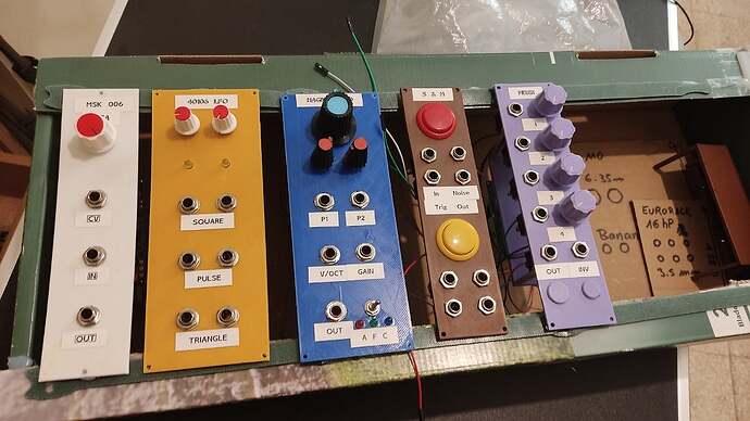
My build progress

I agree, CircuitPython is very fun to use.
I was working on a similar project recently, a sort of combined Big Button sequencer and sample player à la wav trigger implemented in CircuitPython on a Raspberry Pi Pico.
But then I realized that CircuitPython is interpreted and uses garbage collection and I got afraid that the garbage collection cycle could interfere with the timing of the sequencer.

How do you deal with that potential issue?

I’ve been experimenting with some techniques, although I can’t make any recommendations because the code for this is very early, for my part. I’ve been working from the example code that the Neotrellis version of CircuitPython has, which holds the samples in memory in an efficient manner (it’s not for anything more than a percussive hit so samples don’t overlap with themselves and are fully loaded into memory before any sequences play) - those constraints help with memory management, and garbage collection hasn’t been an issue so far. The audio playback is baked into CircuitPython on this board as well, so it’s pretty well optimised, and there’s no audio processing taking place so no intensive maths.

I’d already planned on taking care of garbage collection manually, and I’m using the asyncio library to manage the task scheduling. My day job is as a JavaScript developer so I’m kinda familiar with cooperative multitasking workarounds!

If I can’t make it work nicely, I’ll go back to writing code with Arduino. I hope it’s not going to come to that though, I’ve got 120MHz of ARM processor and I’ve achieved more with less in the past - and CircuitPython is so nice…

3 Likes

I didn’t know that was possible in CircuitPython.
How do you do that?

I’ve not tried it yet - I’ve been trying to get back into a ‘work’ mentality - but this is what I’ve been looking at: Overview | Memory-saving tips for CircuitPython | Adafruit Learning System

1 Like

Interesting documentation, thanks, but I think I’ll stick with C/C++ (or Verilog) for timing critical stuff and limit my use of CircuitPython for quick and dirty experiments.

3 Likes

One assembled EuroPi. It’s helpful having an RS trade counter a couple of miles away, it meant I could get the correct buttons and the surface mounted version of the op-amp I didn’t have. I found some adaptor PCBs in the drawer and it resulted in the correct footprint for the design.

It’s pretty damned good! Wish I’d got the panel in the right thickness instead of absent mindedly accepting 1.6mm, but I discovered that the gaffer tape I have is exactly 0.2mm thick. Two layers on the back, at the top and bottom, makes everything the right thickness for uniform panels (and importantly, allows the screws to hold it tight).

I’ve got enough to build one more, before I have to replenish stocks of bits I hadn’t thought of - I’m almost out of 1k resistors now!

5 Likes

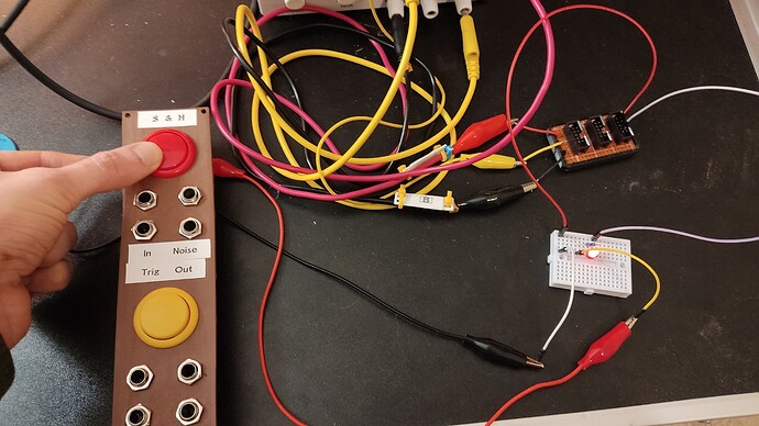
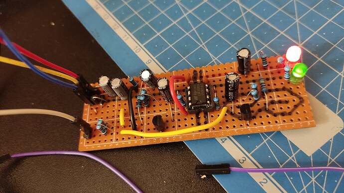
Working on a dozen of things at once and making progress on none lately, but at least I made this little white noise board today… Only partially working, one channel is silent, the other has insufficient levels. I hate stripboard.

But hey, even if I can’t fix it, at least it should work as a temporary daughterboard to make a Sample & Hold module. I still have a working reference build on my breadboard I can poke to verify which numbers I’m supposed to see at various points of the circuit.

3 Likes

and now I slept on it


5 Likes

I made this case out of a broken bug zapper.
Still need some mounting rails and some horizontal kosmo modules for the bottom :slight_smile:

8 Likes

I built more holders and a placeholder

(german insider: probably PO-257)

8 Likes

As they say: a picture can say much more than …

And now try to spot it in here:

11 Likes

Would be better called “Wasted-Space-O-Matic” :slight_smile:
Or maybe “Placeholder-O-Matic”…

3 Likes

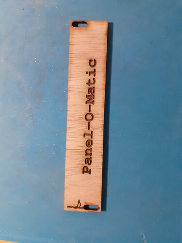
Still waiting for the panel-o-matic 3000 deluxe platinum edition

2 Likes

Or Blank-Panel-O-Matic.

2 Likes

You are on the waiting list, just be patient :wink:

2 Likes

Finish my arduino light trigger


all build detail here

10 Likes

Eminem’s Without Me playing in the background:

:musical_note:Guess who’s back, back again :musical_note:

1 Like

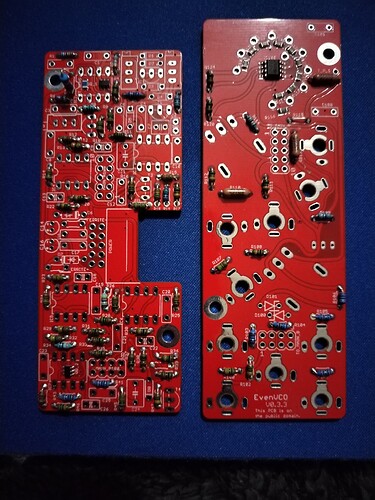
Started work on the Even VCO, had one slip up and soldered a resistor in the wrong spot. Easy fix and I got to use my scope and component tester.

These resistors are tiny and the codes are hard to read. Glad I caught it now rather than later.

Got loads more to do tomorrow =D

6 Likes

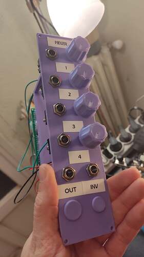
Built a mixer module and a faceplate for my next S&H module!

I’ve started to use CadQuery to make my faceplates. I find it easier to work with than OpenSCAD, SolidPython, or FreeCAD.

The faceplates are entirely defined in code:

Open to see code
import cadquery as cq

# Diameters account for tolerance and thermal expansion

# Base panel
panelWidth = 50 # Kosmo widths are multiples of 25
panelHeight = 200 # Kosmo height is 200
panelThickness = 2.4 # Standard PCBs are 1.6mm, not strong enough for a print
m3Diameter = 3.3
panel = cq.Workplane("XY").box(panelWidth , panelHeight , panelThickness)

# Holes for M3 screws in the corners
panel = panel.faces(">Z").workplane().rect(panelWidth - 6, panelHeight - 6, forConstruction=True).vertices().hole(m3Diameter )

# Holes for jacks. At least 16mm apart
jackDiameter = 10
jackLocations = [
    [25 - 12.5, 60],
    [25 + 12.5, 60],
    [25 - 12.5, 80],
    [25 + 12.5, 80],
    [25 - 12.5, 160],
    [25 + 12.5, 160],
    [25 - 12.5, 180],
    [25 + 12.5, 180],
]
for pos in jackLocations:
    panel = panel.faces(">Z").vertices("<XY").workplane(centerOption="CenterOfMass").center(pos[0],pos[1]).hole(jackDiameter)
    
# Holes for buttons. At least 31mm apart.
buttonDiameter = 28.4
buttonLocations = [
    [25, 30],
    [25, 130],
]
for pos in buttonLocations:
    panel = panel.faces(">Z").vertices("<XY").workplane(centerOption="CenterOfMass").center(pos[0],pos[1]).hole(buttonDiameter)

I’m using cheap Aliexpress clones of Sanwa buttons (I’m not dropping money on the real stuff unless it goes into actual gaming hardware, lol). They have the same hair trigger that characterizes the brand. The circuit for that one is a WIP until I buy the components or find / figure out a circuit that works with my stock.

I also worked on building the Moritz Klein Clipping Distortion Mixer, with 4 channels instead of 3.

Sadly, I couldn’t get the clipping distortion to work. But everything else worked perfectly on the first try. I don’t really care for the distortion feature, in fact, I should have added a 5th mixer channel and skipped it entirely, which would have let me use a smaller op amp. Too late for that, so I added printed plugs in the holes where the diode clipping circuit would go if it worked:

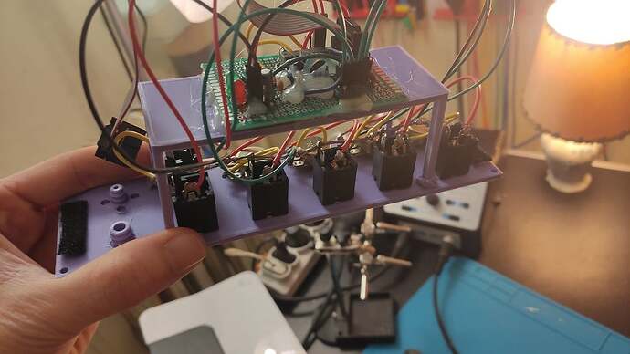
There supports are welded to the plate using a 3d pen. It’s a good technique for parts that won’t bear a significant load but is definitely not something that will resist mishandling.

The protoboard is hot glued to the support, and also on its surface. There’s resistors that overlap each other on the protoboard, so I’m freezing them in a known good configuration. Dirty? Certainly a good enough technique for a surprising amount of big brand electronics, so good enough for me.

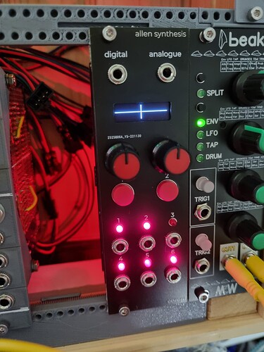
I will really need a real rack soon, and also a way to power up my modules, my test busboard made of stripboard can only power 3 at once, I could build a bigger one right now, but I’m expecting busboard PCBs soon. I’ll also need a PSU when I finally make a decent case (don’t worry, as much as I love my janky 3D printed builds and cheap components, I’m serious about safety for the power supply)
8 Likes

Nice progress =D I’ve got a mixer I need to rework. How’s the overt done? Would be good for CV stuff.

As for PSU, have u had a look at Kristian from Modular in a week’s tindie store? He’s got some cheap, small PSUs that I’ve been using in my cases. Not many problems other than sometimes one of the rails doesnt power up.

1 Like