My build progress


Today i finished the CGS pentode VCA/wave folder. It’s the gold module in my low voltage tube voice.
I used a chinese 6j1 on +/-12v. Might try with a philips ef95 :slight_smile:
It works ok but does not mute all the way, might be just one resistor to lower the grid voltage a bit more.


Also i made a 7 pin tube to breadboard adaptor, only for low voltage of course :slight_smile:
Will make a 9 pin version this week

9 Likes

Any chance you can publish a schematic or refer to one?

3 Likes

Broke out the soldering iron this morning and soldered up a load of NeoPixels; then ordered a bunch more arcade buttons. This afternoon I wired up my MIDI socket, as some 220R resistors turned up. I plugged a MIDI cable from the Pico to the Noodle Toaster and plugged that into the breadboatrd of the mki x es.EDU VCO I’ve got going on.

It’s currently setup with an octave down, octave up and two note buttons. It looks like the Noodle Toaster doesn’t do note_off messages, so not sure what to do about that at this point. I also can’t decide if I should retrigger all playing notes when an octave button is pressed, or only apply it to new button presses. I might do both and make it configurable.

Hopefully the last of the bits will arrive in the next couple of days I can get a basic faceplate made to hold all the buttons.

2 Likes

http://www.synthpanel.com/modules/cgs27_tube.html

I used a 6j1 tube that came with the cheap ‘preamp’ you can get on aliexpress. The pinout is different though, but the same as ef95.
I didn’t have 39k so i used 33k.
My pots measure around 25k and i used 4.7k instead of 10k resistors because i didn’t have any.
It works ok, although it doesn’t mute all the way.
It might be an easy fix by changing the 680k or the 47k on the cv side, to pull the grid a bit more negative at 0 volt cv. I am going to try that this week.

Edit: also i run it on +/-12.6 volt

4 Likes

In regards to 12AX7 tubes: why not supply at least 48Vdc to the plates with appropriate plate resistors to at least bring the valve up to a working voltage. 96Vdc through voltage doubling would be better.
If 24Vdc is an option the tube still is starved - the KORG NUTUBE 6P1 tube thingy can operate at that nominal voltage however.

I see all these designs that just don’t go there and leaves me wondering. I guess I’m just the victim of too many years tech’ing tubes at high voltage performance.

5 Likes

I don’t really like the sounds of starved circuits myself either.
I build tube amps too and i am getting started on a high voltage tube synth as well, but there are some low voltage designs that i really want to try as well. :slight_smile:
(I’ve hinted at a high voltage tube project before in this topic, i am not going to share it untill i have one of the modules finished and working)

With low voltage circuits, i worry less about connecting it to my other stuff, and it’s also a bit cheaper because i don’t need high voltage capacitors.
The safety valve in the picture will probably not stay in that case, i don’t want to use op amps in the signal path for this synth voice. Transistors are allowed but only as emitter followers.

The vco uses an ef80 (6bx6 i think) the vca uses a 6j1, the vcf (not going to be the mean sucker like on the label) will also probably use one of those two tubes.
If there’s going to be a distortion in there i’m going to use an ech83 heptode triode one that i’ve made already. Those tubes work just fine on 12v and were used in car radios and battery designs on 12v.

I very much prefer 12au7 (ecc82) for low voltage and i have a lot of them. If i need any double triodes for this synth voice i will use those. The only 12ax7 is in the rene schmitz exponential converter, it doesn’t work yet because i don’t know how to connect the virtual ground, but i am going to try that with different tubes as well.

3 Likes

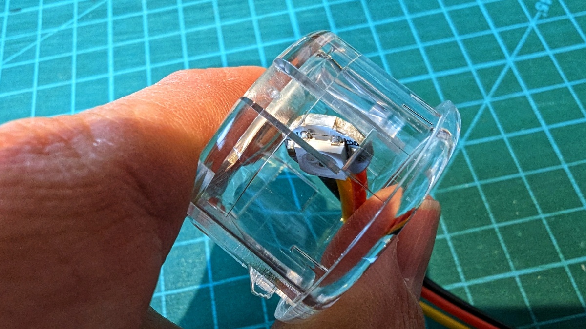
More progress on my interpretation of the Super Simple Midi Keyboard today, with the recent arrivals in the post. The first problem, was the Seimitsu PS-14-K 30mm snap in arcade buttons differ from the ones Adafruit sell, so the NeoPixels mini buttons don’t fit.


No problem when you have a craft knife though. Although it turns out you can slice down either side and then just push the resulting tab out with a small screwdriver. Wish I’d discovered that on the first button, rather than the second last one…


The next problem was the NeoPixel buttons not fitting into the base plate holder of the 3D printed insert. Given that Adafruit sell the NeoPixel buttons, and have the 3D printing files in one of their tutorial, I naively assumed they just fit. I’d sent Fancy Impact Blasters (FiB) a button, just to make sure the 3D printed inserts fitted, I should probably have sent them a NeoPixel too.


Nothing a bit of fine sandpaper and a small file couldn’t fix though. I’m not sure what use sending FiB a NeoPixel would’ve been, as each button seemed to differ slightly in width; presumably from differences when snapping them apart. I had to sand down each button and file each insert as a pair, as most buttons wouldn’t fit other inserts. :person_shrugging:


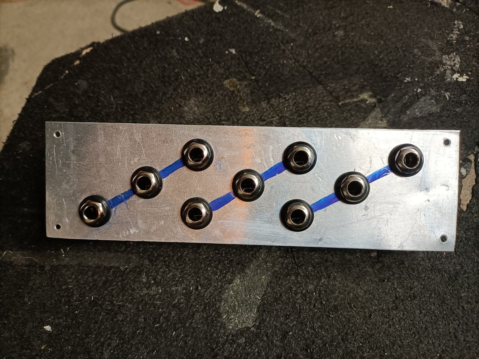
There was a break in the rain at this point, so it was out to one of the sheds to drill some holes. If I’d had my shit together, I’d have had a case laser cut by someone. As it was, I own 29mm and 30mm hole cutters, from when I used to fly high power rockets. After a test hole in an old plastic container, I decided to go with the 30mm cutter, so marked up the acrylic. Then it was time to break out the big drill.


Fourteen holes later, it was back to the desk to make some wiring looms and do a spot of soldering. I needed to add a further two NeoPixels to the chain and make a wiring loom, but was waiting on drilling the face plate to determine the length of all the wires that would be required. It took ages to crimp the common arcade button line; and I ran out of black wire, so will have to order more.

Unfortunately, during all the sanding and filing, a wire had fallen off one of the NeoPixels, and another needed some better soldering. With that done, I cleaned the back of all the NoePixel buttons with IsoPropyl and a toothbrush, which dislodged yet another wire, so out came the soldering iron again…

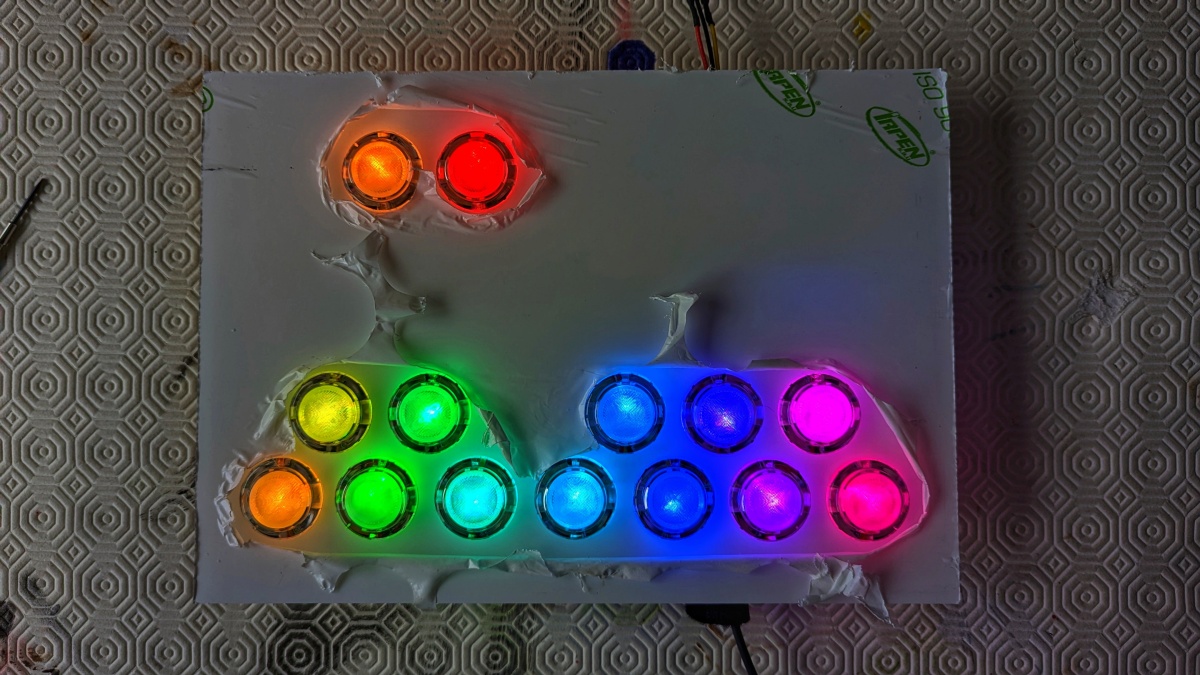
I though it best to test all the NeoPixels before trying to thread them into the arcade buttons, and I’m glad I did. Only half the chain were illuminated, as it turned out one of them had blown. I’m going to assume I damaged it while sanding or filing and then the IPA finished it off.


So the soldering out came back out, and I gave a little thanks to The Pi Hut for sending me a few spare NeoPixels in my last order. With the chain all illuminating after a small code change, it was time to thread the NeoPixels into the buttons. Except I hadn’t had dinner, and it was 20:00, and I was tired, so in a break from my normal, I put everything down and came inside.


Given the state of my soldering, I figure that I should be awake and on it, before attempting to thread all those NeoPixels through those buttons. So that’s tomorrow mornings job.

9 Likes


Triple passive filter that @saint_et_moudulard posted in the passives topic :slight_smile:

9 Likes

Deja vu!

11 Likes

Years ago an ingenious engineer built this whacky All-Valve synthesiser. Dude lived near Stanford, Ca or Alta Vista … 2000 or so he had a fully working system

1 Like

Maybe he can help me with the LFO :slight_smile:

1 Like

Kassutronics Wavefolder. To go behind a Kosmo front panel (details not worked out yet) hence the lack of board mounted pots and jacks.

10 Likes

METASONIX on the WEB … very interesting stuff …uses TV tubes and such. Check out what he has to say about the RK7 VCO

3 Likes

A frustrating day yesterday, that I didn’t quite get round to documenting last night. Spent a bit of time in the morning threading the NeoPixels through all the arcade buttons and confirming they worked. You can clearly see that some have fallen out of their holders, as they aren’t centred in the button; I’ll need to buy some superglue to fix that.


I then added all the rest of the wiring and was slightly perturbed when none of the buttons seemed to generating MIDI notes. After a lots of faffing, I broke out the multi-meter, stuck it on continuity and found out that the button inserts are too tall, and all the micro switches were on all the time. Here’s the switch plunger with a normal insert:


And here’s the plunger with one of the NeoPixel inserts:


Unfortunately I had other things to do for the rest of the day, so I couldn’t sort it out till this morning. Before work, I took each button apart, again, took the micro switch out and sanded down the plunger. Then I put everything back together and it now works!


Each octave has a colour associated with it, at the moment all note butts take on the same colour as the octave. The two buttons at the top are for going up and down an octave, their colour indicates the colour the notes buttons will take when you switch.

If you run out of octaves, the buttons go dark:


This also highlights that five of the NeoPixels appear to have a slightly different hue, I’m not sure what that’s about. I think I need to come up with better colours, with more saturation; suggestions welcome.


The next job is to solder this lot onto some breadboard…


Then try and fashion some sort of case.
Then add a screen and a rotary encoder to change some of the settings on the fly, and maybe display some other things too.

13 Likes

Been a little while. Personal issues and health issues have kept me away from my atelier for a while, and I found myself with the same circuit exactly the way I left it 3 weeks ago.

What does it even do? What are those weird annotations in the margins even about? Hell if I know!

Still, I left myself a note to try a different voltage divider. I tried it out and it seems to work, for some reason. I’ll call that “build progress”.

10 Likes


er-808 drum machine finally almost done just some bug fixing and tweaking !

27 Likes

pretty, very neat build

2 Likes

Progress on a dual VCA module derived from David Haillant’s Simple VCA. The one on the left half has been tested and works really well, the one on the right is in progress now. Front panel is 3D printed 4HP Eurorack size. 3.5mm jacks are stereo ones that I got loads of really cheap a few years ago - I’ll either not connect the ring connection or cut it off (I’ve done this A LOT).

I’ll have it finished on Monday :slight_smile:

8 Likes

I went to a lot of trouble putting those diode and power header footprints in, you know! :laughing:

10 Likes

I was going to put in the diodes but I don’t have any of the right ones on hand, so I started ordering… And then I thought “wait a minute, my power connector can only go in one way anyway” so I used the footprints as decoration :laughing: the caps are a bit dinky, but the right value at least!

3 Likes