Noise module finished! Technically the pink and blue noises are just pinkish and blueish noises (white with low and high pass respectively) but I am fine with it 
Now waiting for the sample and hold chips…
Noise module finished! Technically the pink and blue noises are just pinkish and blueish noises (white with low and high pass respectively) but I am fine with it
Now waiting for the sample and hold chips…
A riot of color. I love it <3
looks great , love the colors on the custom panels !
I’ve been trying to upload a picture but each time the upload is timed out. I tried several browsers on 2 machines. Same result. Anyone?
This happened to me last week. I had to wait a day and it went back to normal.
Did you find out what was the cause?
Nope! I tried on my phone, Linux box, Windows laptop, fast WiFi, slow WiFi, VPN, no VPN.
@Caustic can look at the logs and find out though.
(discourse has excellent logging for troubleshooting and debugging things like this)

Breadboard to guitar pedal/Kosmo adaptor.
Currently prototyping a cmos distortion for bass guitar
Edit: yes i see that i missed the ground connection from the jacks to the breadboard, it was early in the morning 
Finishing up cardboard box
Another sweet build by @Dave today, his Brenn quad LFO. Of course, I couldn’t help myself from modding it…
And yeah, it still needs knobs, but left my screwdrivers in the new house damnit…
This module offers 4 triangle LFOs with bipolar and unipolar outputs, and a global CV control. First, I swapped out the timing caps to create 4 separate ranges of LFO speeds. Then, I realised I didn’t really need to unipolar outputs, and was able to repurpose the circuit to provide summed outputs. Each LFO now has an extra output of itself and its two neighbours summed. This creates some pretty funky waveforms, like this one:
Having 4 of those with global voltage control is gonna be super fun, thanks @Dave !
I love this idea! Good hack.
Oh yeah, this reminds me to add a summer and also an offsetter module to my synth. I like to separate out functionality into different modules but I really like your approach too!
Ah, just realised that you also let the panel produced by the PCB manufacturer. I guess you are using aluminium panels?
I got these pcbs and panels from @Dave. Indeed the panels are produced by the pcb fab house, though these are normal fr4 panels. For my own modules, I do use aluminium panels, both are fine IMHO.
Yeah, I was thinking about doing more PCBs and CNC in general and going away from wires, but I was always too lazy figuring out where to buy PCB mountable pots and jacks, let alone the KiCAD footprints and the hassle with the dimensions  I’ll think about it… for now I am hand-drilling and sawing and putting wires, which of course is sometimes quite a pain
For Kosmo designs by Sam and others, the commonly used jacks are ones like these (you might prefer another vendor where you are, but you can find ones like these in a lot of places):
and board mounted pots are often these
although I sometimes design for these, which tend to be out of stock less often, and can be had with 6 mm shafts for which you can get knobs on AliExpress much more readily:
For the 9 mm pots there are standard KiCad library footprints, my preferred one is
Potentiometer_Alpha_RD901F-40-00D_Single_Vertical
while for the 16 mm pots and the jacks I use footprints I made which you can find here:
https://github.com/holmesrichards/aoKicad/blob/main/ao_tht.pretty/Potentiometer_Alpha_16mm_Single_Vertical.kicad_mod
https://github.com/holmesrichards/aoKicad/blob/main/ao_tht.pretty/Jack_6.35mm_PJ_629HAN_slots.kicad_mod
WARNING: In the KiCad footprint library you can find other board mounted pot footprints, but in most cases while the CCW pin is pin 1 on the horizontal footprints, on the vertical footprints it’s pin 3. Only the Alpha vertical and I think a couple others have the CCW pin as pin 1. I don’t understand it but there it is.
For fabbed panels we have a whole library of Kosmo-standard holes:
Lovely, that wrap-up makes it much easier, thanks!
Ah yeah, speaking of CW and CCW: I am always confused since this seems to be a mess-up in many strip board layouts as well. Or maybe I am just doing dumb mistakes Whenever there is no hint on the orientation and I only see pin 1, 2, 3, I always assume that pin1=CCW, pin2=wiper and pin3=CW, but now that you mention that it is different on some pots, it now makes sense.
I recently built a module (I think it was the Thomas Henry BD++) and every pot worked as expected but the volume and the decay, which were the other way around. I double checked and I have not made a mistake, but I’ll also check my pots again
There are gremlins that change pots around no matter how many times you check.
I was looking at some old ARP schematics and they have no pin numbers but every pot has an arrow, sometimes with a “CW” label:
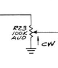
Might add that to my footprints.
Added:
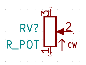
That symbol will be a total lie if used with the wrong footprint, but that’s nothing new.
Yeah! Please do that! if you put in the default footprint there is no room for error anymore (okay, that’s never the case, but it makes errors harder)! Also: your symbol library and footprints are AWESOME! I am using them on all my current projects! Btw: do you use them as project specific libs or as global in kicad?


