I think it is really interesting how we each use a different method for creating our panels and PCBs and how we get them to line up correctly. I create my PCB first in KiCad. I determine the hp size, place the pots, jacks, switches, etc… to what works best functionally and then I take a screenshot of the PCB and import it into illustrator. I resize the screenshot to the correct size and then put it as an overlay and lay out my panel on top of it. That’s the process that works for me. If I decided to make my panel first then I would likely do it in a similar way to how you do it.
3 Likes
Hi everyone.
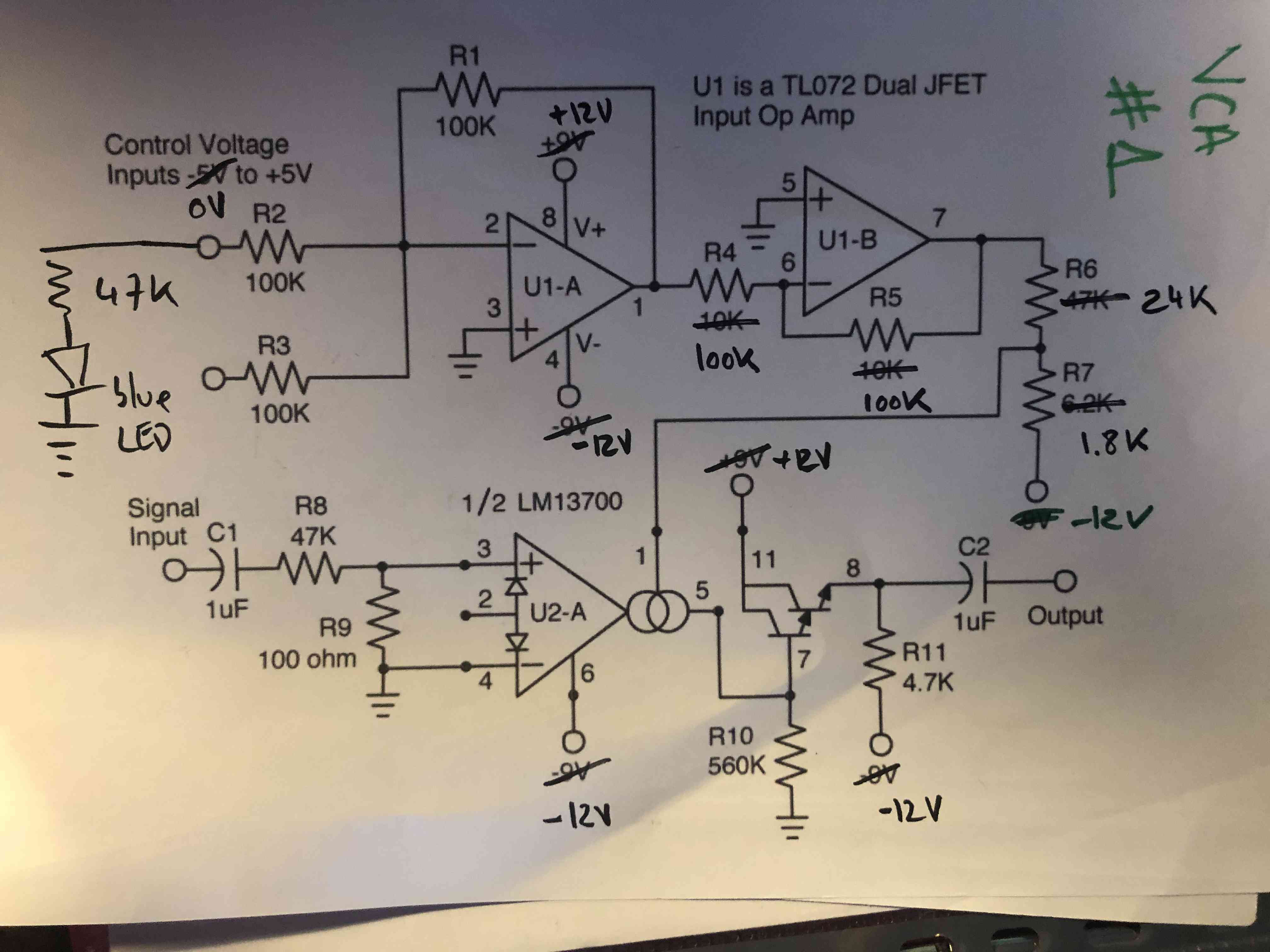
Just finished a 2x2xVCA today (it’s 2 VCA based on a LM13700 and 2 VCA made with AS3360, from LMNC)


It’s really nice to have 4 VCA now ( I use to have only one for a long time). The 2 design sounds a bit different. The AS3360 output is louder (I think it is because it is supposed to get something between 0 - 2V and I send 10V max with my ADSR?) than the LM13700.
I wanted to keep the LM13700 design cause I think it “sounds” better, even if at 0 V in, there is still some output left.
Anyway here the schematic for the LM13700 based VCA. Was supposed to work on -/+ 9V, did some modifications for fitting in 12V (I did it kind of blindly cuz I’m not an electronic expert, but I use this one for 2 years with no trouble, so I guess it is good)
7 Likes
My attitude is I want to design the user interface first — where the pots and switches go, sizes of knobs, and so on — and then make the PCB layout accommodate that. Of course it’s rarely that linear. Usually there’s some back and forth between panel and PCB design. But I try to give the panel priority when feasible.
4 Likes
Same here, though my method involves shuffling knobs around on a piece of paper  .
.
2 Likes
I design the panel holes in Onshape where it’s easy to define parametric dimensions and shuffle holes around. Then I 3d print a prototype a couple of layers<1mm thick to check the layout and ergonomics. I export the DXF to Inkscape, design the silkscreen, then import both to Kicad for the panel and PCB.
3 Likes
Autocad for me, only because I have a fair amount of experience with it, but a similar process, Draw panel, place components, procrastinate, move stuff, draw the outline of pcb’s, place markers for headers, import into kicad.
However, the Autocad > Kicad experience can somewhat dampen enthusiasm.
2 Likes
thats exactly what I did with EuRolz - Designed the Panel first, figured out how the bullet connectors and all that were gonna line up and then built the circuit around the parts 
Its a good method!
Like @popflier said - its really interesting how we all do things a touch different tho.
3 Likes
Today a quick test of some new modules.
1 ok, 2 ok … i have 10 modules working well
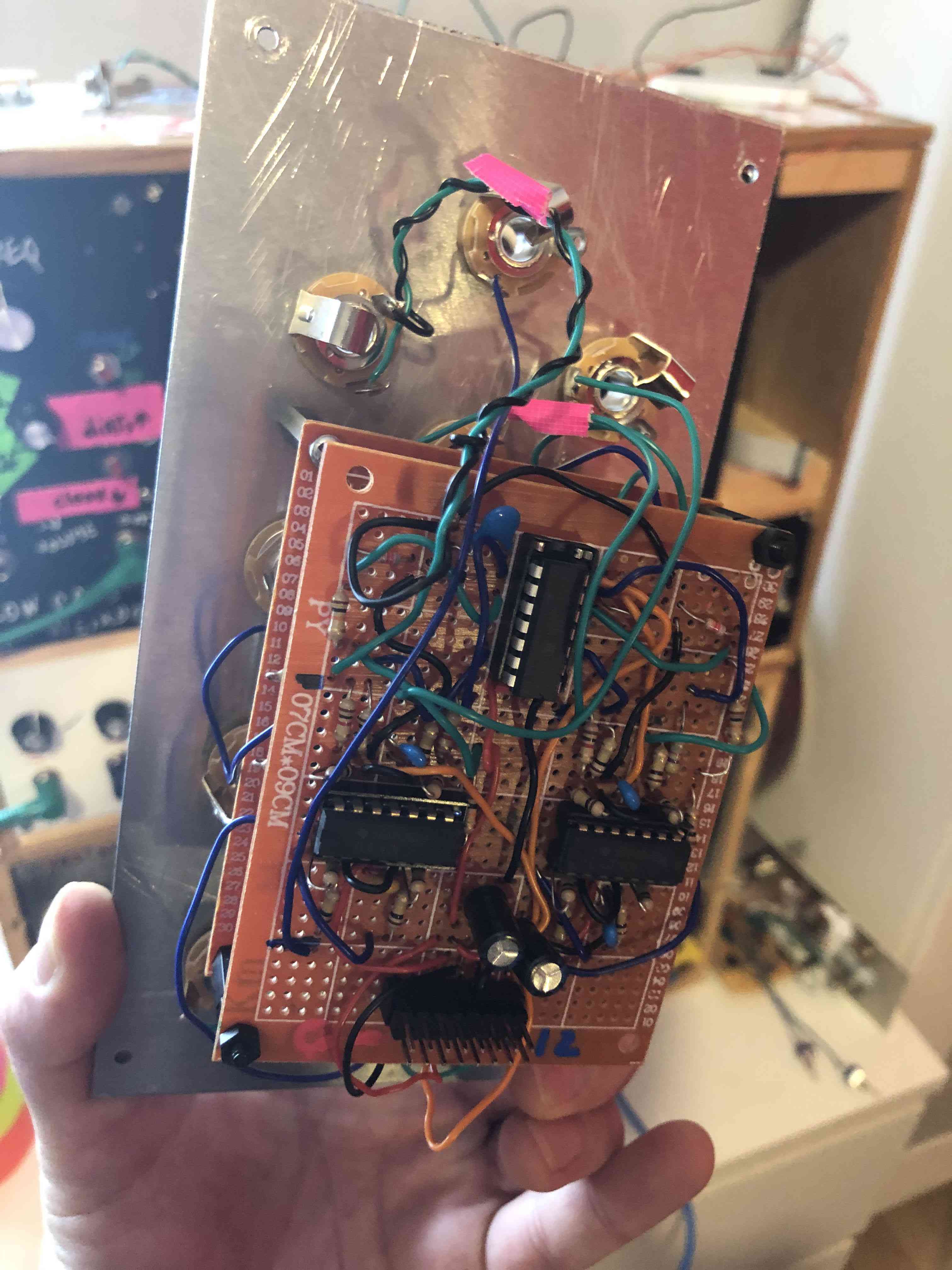
but now it’s been 4 hours that I got annoyed on a dual ADAR (which I have however already done several times and not a very complicated circuit), the 1st works well but the 2nd not at all !
this is the same circuit 2 times, I have re checked everything over and over again, re done some soldering, change the TL072, continuity test, …
and i have some strange negative voltage with the multimeter by comparing with the one that works
Example, i test with a constant gate on each, and i’ve near +10V on the one that works and on the same opamp pin but on the one that does not work gives me -10V … ???§§§?././/??
at this time I don’t understand anything anymore, I’ll watch it tomorrow again.
2 Likes
Nice! Can you reveal the type of Darlington (the pnp-transistor) you used in this design? And please explain what made you change the R6 and R7 values.
1 Like
I guess the darlington is the one that comes inside the lm13700. 
1 Like
Given the pin numbers shown, I don’t think guessing is required… definitely the LM13700.
R4 and R5 should be able to stay at 10k. As long as they’re equal you’re okay, but that stage doesn’t need the 100k input impedance (the first stage needs more, although the LED mod lowers it from 100k to about 30k) and lower values will decrease the noise floor.
Right, because of the unusual ‘symbol’ for the LM13700 I missed the pin numbers!
2 Likes
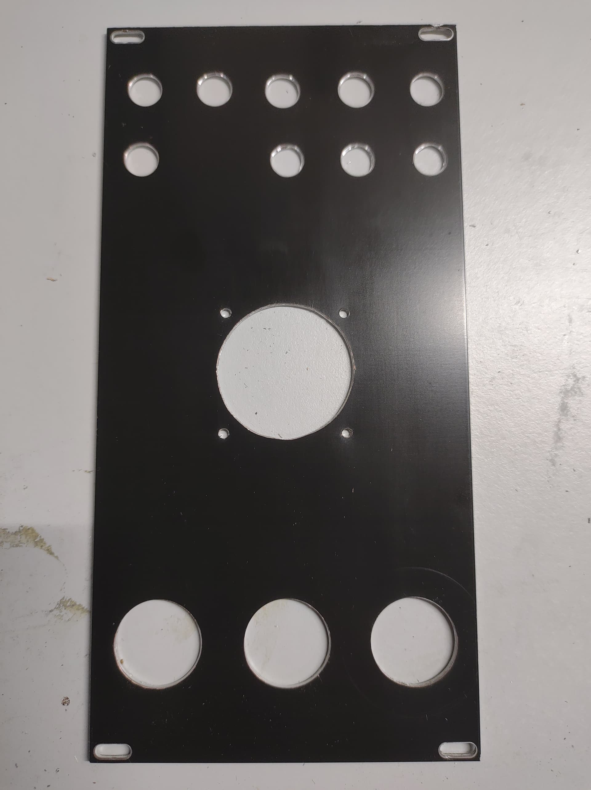
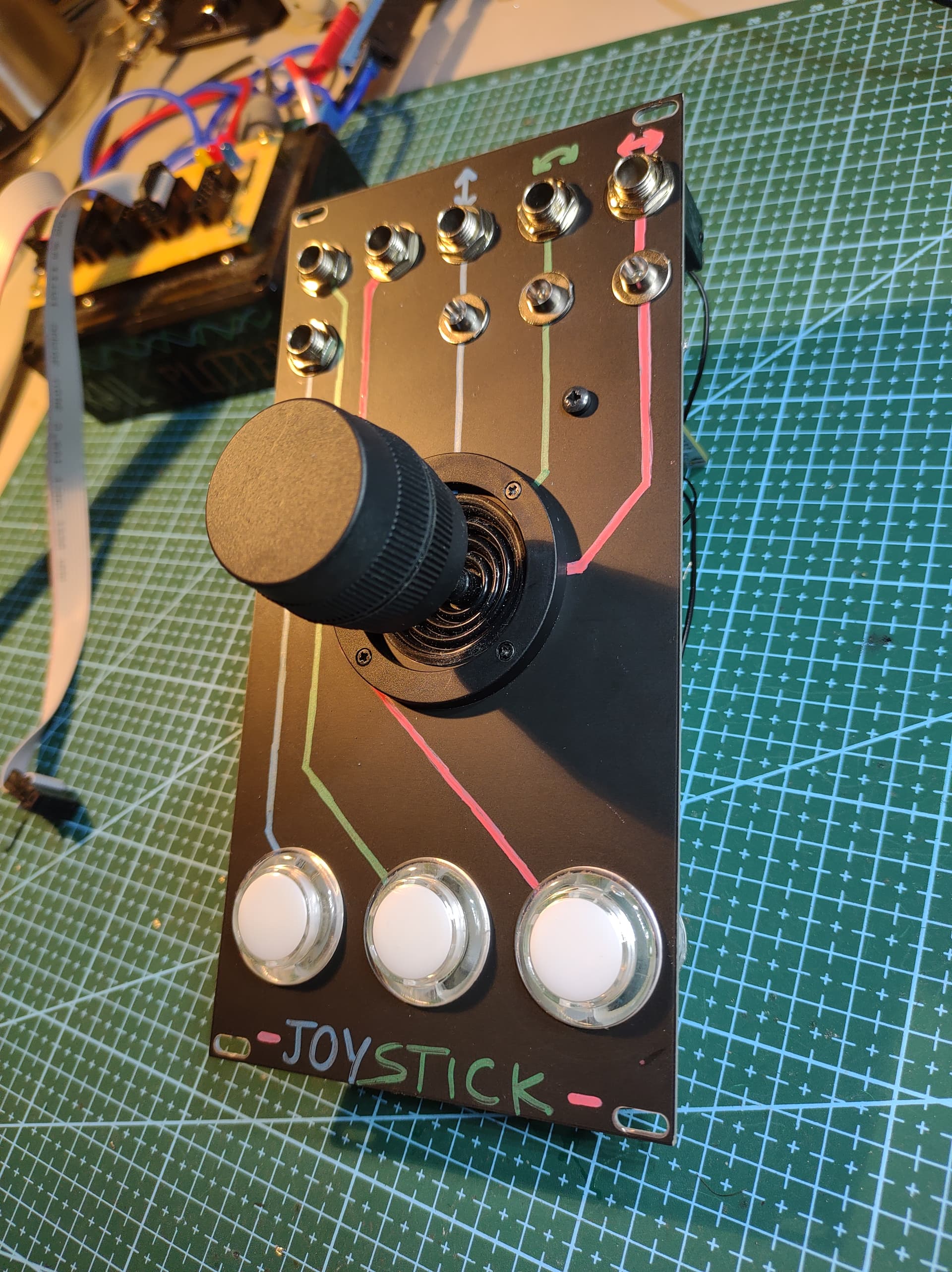
Finally got around to building stuff again! Did this three-axis joystick controller, with an additional three arcade buttons. Was a little bit bummed to find out that the third axis (rotation of the shaft) actually has an antilog taper to it, but oh well. Ended up soldering a parallel resistor across the bottom half to sort-of straighten it out.
This was the first time using aluminium blanks from JLCPCB, and it held out pretty well, didn’t see the need to repaint it.

13 Likes
A nice big joystick 
After spending hours yesterday looking for the failure of my new dual ADAR without success and almost a start of madness
Today it took me 10 min to find that a resistance was not of good value. I replaced it and everything is working fine now.
I continued to test a few modules and I’m happy because all of them work, there are still 4 or 5.
6 Likes
Nice, where’d the joystick come from? I have a cheap 2-axis one I’m planning on using but that third axis is interesting. Any way to swap out the antilog pot?
1 Like
don’t say it, don’t say it…
I got this one off aliexpress, the model number is JH-D300X-R4. They also sell a ‘4 axis’ one, which has an additional push button on top.
The 3rd axis put is buried inside the xy carriage, so I doubt you’d be able to get to it without destroying the whole thing. Also the range of motion seems smaller than a standard pot. I’ve put a 10k resistor (the pot value was 17k, oddly enough) across the bottom half of it, so new the centre position of the knob sits mostly in the centre of the pot. Still not linear of course, but fine by me.
3 Likes
Thanks for your suggestion, I will try that! I have to study more the op-amp in order to fully understand what’s going on here :D.
1 Like
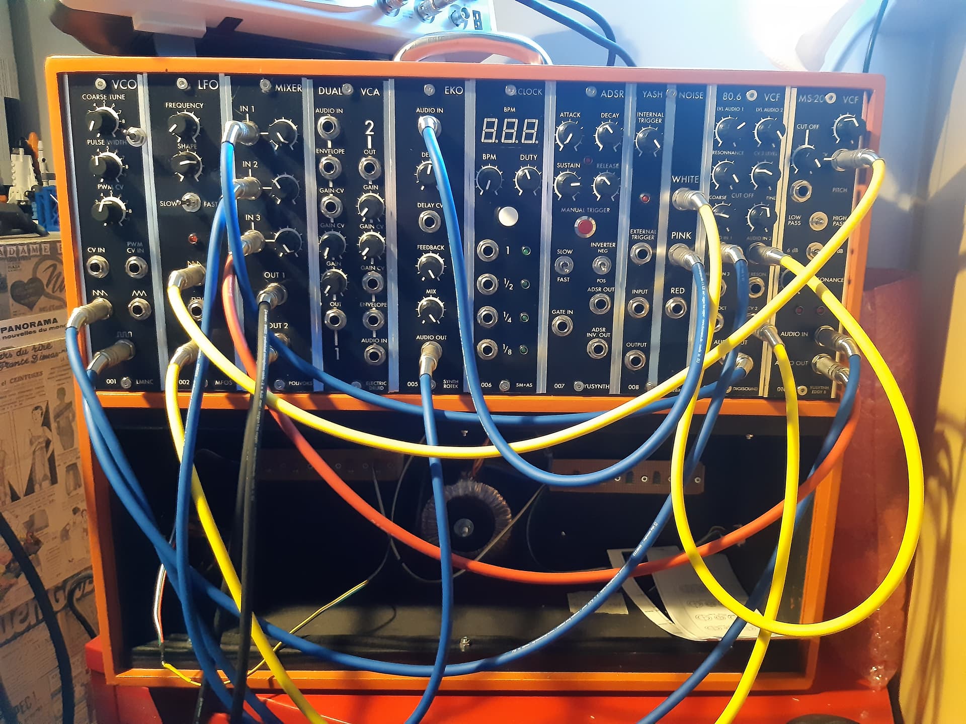
First half of my first cabinet is complete! Quite happy with what I have accomplished in the past three months.
I began to plan the other half: midiCV, ring modulation, polivoks VCO VCF VCA ADSR, LFO and more VCAs…
10 Likes
Thats a nice setup you have built yourself.
3 Likes
Well done! I like your panels, they look very professional with a nice Moog vibe. What have you used for that clock module?
4 Likes