Finally, the Dual VCEG build is complete and (mostly) working!
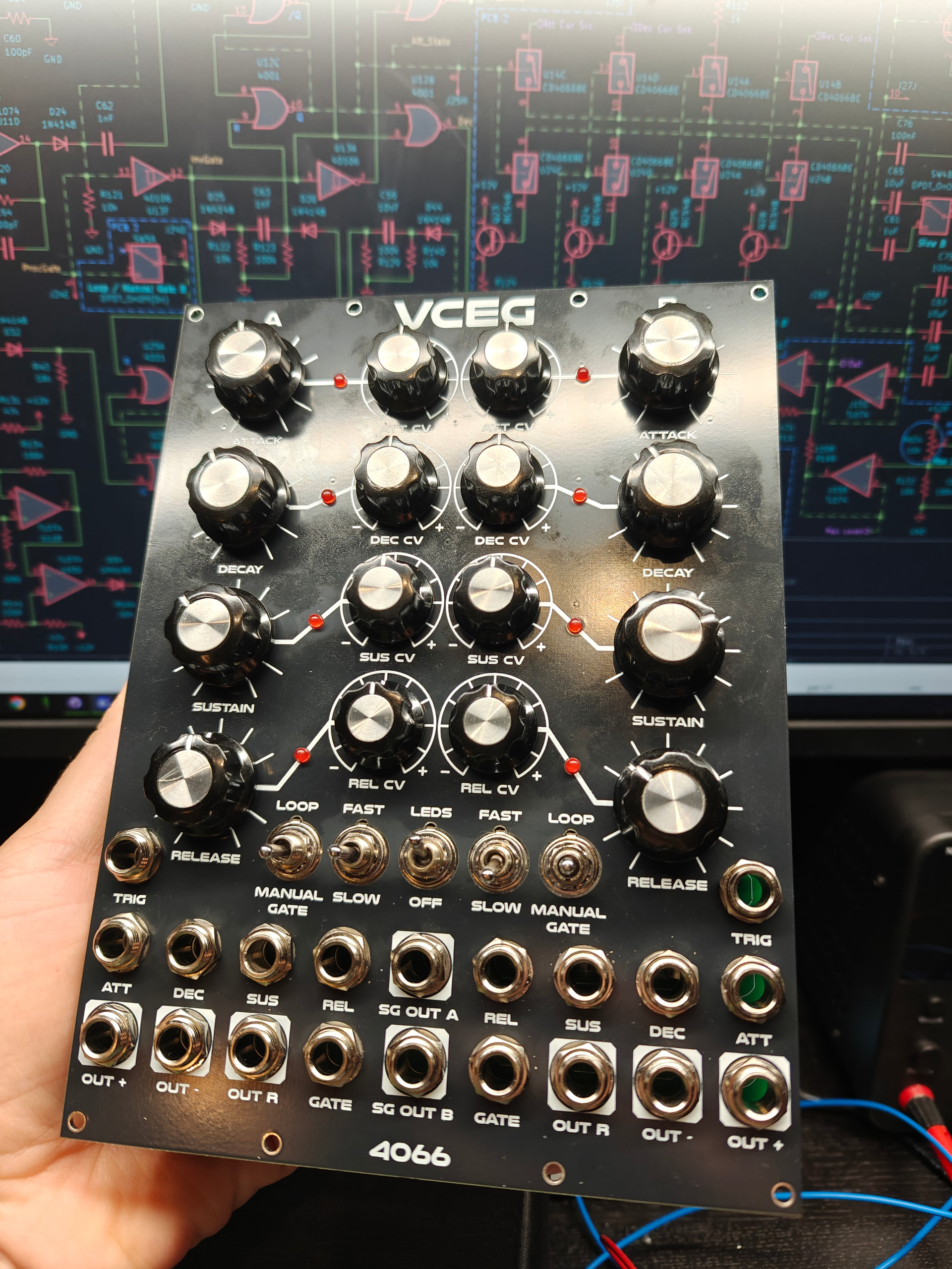


The base circuit is inspired by the MFOS ADSR, which I expanded with voltage control for all parameters, LEDs, inverted output, sustain gate output, “release only” output (which doesn’t work…), super fast mode, and ADR looping. All CV inputs have their own attenuverter.
Demo: https://youtu.be/IbwRrnVJeVw?si=PNbH8NBv8-50m8Ea
Git: GitHub - DeMarco/DMH-VCEG
This freaking module gave me so much work to design and test that I’m really looking forward to an easier project next…
Unfortunately I still need to redesign one of the PCBs with an improved solution for the “release only” auxiliary envelope (inspired by the Moog Grandmother VCA’s “keyboard release” mode). For some reason it works perfectly on the breadboard, but the BS170 MOSFETs I used keep going bad on the PCB. I’ll just do away with them entirely and use one more CD4066E instead. With that, the module will count 26 ICs and exactly 200 resistors (plus all the rest), so that gives a hint on how much of pain in the butt it was to build. I never thought a VC envelope would be such a “non trivial” thing to make.
When the new PCB version is ready I’ll inform it here. Will also write a procedure on how to calibrate the thing if anyone is interested.

