Hagiwo 6ch drum sequencer + 4x4 matrix keypad

Hi everyone! This is my first post on this forum, a couple of months ago I started to build diy modules and including a module from @Hagiwo (https://note.com/solder_state/n/n17c69afd484d), but I found it very uncomfortable to control (personally for me, no offense to Hagiwo), and I decided to try to add a matrix keyboard to control the steps of the sequences, I’m happy to report that I got it! I am not an expert in programming, but I have some basic knowledge, the code works stably and no problems are observed, but the code itself may be written incorrectly, that’s why I turn to this forum).

Friends, let’s make an effort together to finalize the code of this module, so that our community has a simple, convenient, and most importantly Cheap trigger sequencer for our drum modules!

Here are my ideas for finalizing this project:

  1. remove some functionality (AUTO mode) to make room for other functionality.
  2. Add Fill mode in MANUAL mode
  3. Make it possible to store/save patterns written in MANUAL mode.
  4. Add a live performance mode (so that you can mute individual channels from the keyboard and play some effects like fill or random steps).

Also on the arduino nano pins A6 and A7 are left unused, they can be used for example for buttons “FUNC” or “LIVE” or “RESET”.

Hagiwo code: https://note.com/solder_state/n/n17c69afd484d
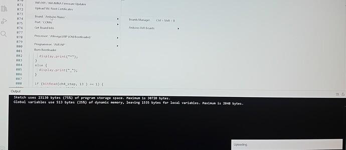
MY sourse code: GitHub - Kozak-derezak00/drum_trig_seq_6ch: in this project is a module 6 channel trig sequencer from Hagiwo, but with the addition of me matrix keyboard 4x4 to control the steps of the sequences, the code is very raw and not attractive but WORKABLE, sketch uses 97% of the resource arduino nano.

6 Likes

3 Likes

ive got me some of these button matrices, thats a neat use case :slight_smile:

1 Like

Let me start by saying that you should not be discouraged by the suggestions I’m going to make here. As a long time programmer who at one point in time also wrote his first program, I know that ones early programs are not ones best. So, keep on going, you can learn a lot by doing and by looking at code written by others.

There are large sections with IF statements that are almost repetitions of one another. By this I mean there is a lot of code that is repeated although the code contains only small changes.

The repeated code can be simplified by using a loop or a combination of a table and a loop where all of these small changes are built into one or more variable. Let me give an example of using a loop. If you look at this bit of code (this is only an extract):

if (bitRead(ch1_step, 15 ) == 1) {
     display.print("*");
   }
   else {
     display.print("_");
   }

   if (bitRead(ch1_step, 14 ) == 1) {
     display.print("*");
   }
   else {
     display.print("_");
   }

   if (bitRead(ch1_step, 13 ) == 1) {
     display.print("*");
   }
   else {
     display.print("_");
   }

This “if-else” is repeated 15 times and can be reduced to 6 lines using a for loop:

for (byte stepNr = 15; stepNr >= 0; stepNr--) {
  if (bitRead(ch1_step, stepNr) == 1 {
   display.print("*"); 
 } else {
   display.print("_"); 
}

The variable stepNr will change with every cycle of the loop and therefore all 16 individual if-statements are executed as they were in the original code.

But there is one more step you can make here.
Since in the present code this section is repeated for ch1_step up until ch6_step, you can add another loop, an outer loop, which loops over chX_step, like this:

for (int chStep = 1; chStep < 6; chStep++) {
  for (byte stepNr = 15; stepNr >= 0; stepNr--) {
    if (bitRead(ch1_step, stepNr) == 1 {
     display.print("*"); 
   } else {
     display.print("_"); 
  }
}

Please check that the start and end conditions of both loops correspond to your code. I’ve not checked this. I merely want to illustrate the use of the 2 loops here.

In this way the number of lines of code is reduced quite a bit. The thing that often occurs when copying code parts and locally adapting them is that one is prone to introduce errors which van be hard to spot. Given that we now have 8 lines in stead of more than 100 (for this part), the odds of introducing an error that you will not be able to spot easily are much smaller. Furthermore, the code is simpler to read, easier to debug and to expand.

There are multiple parts of the code that could benefit from a looping-approach like this.
You will find that you can free up quite a bit of memory once you apply this method and it make your code easier to read.

5 Likes

this looks awesome and after building the original, a very welcome addition!

The one I built is from GitHub - mzuelch/CATs-Eurosynth: Analog Synth Eurorack Modules which also includes schematic and kicad files so it should be pretty simple to add your modification to his version. I may give that a go after the hols.

2 Likes

Built the original but I think there’s something fishy going on. If I power it off USB the display structure looks fine except that every single step is filled with a star (*). Is it supposed to boot like this?

Then if I plug this into my case’s 5V supply things get really erratic but that might be more of a solder issue somewhere. Or would there be any other reason why this works from USB but not directly from 5V input pin?

Are you connecting your +5 V supply to the VIN pin or the 5V pin? Should be the latter. If you were using the +12 V supply it’d be VIN, where the onboard regulator would convert it to +5 V, which would be available at the 5V pin; but the regulator needs at least about +7 V. Alternatively a regulated +5 V supply can be connected to the 5V pin.

If that is what you’re doing then it should work the same as with USB power.

1 Like

Did some resoldering here and there and got this working for a couple of clock pulses until it froze completely. When switching the 5v power off and on again I noticed that Nano’s onboard led kept blinking and some current was even flowing to my panel led as it was also blinking dimly when there was no 5v power applied. After that I soldered another bat43 diode on the +5v line as polarity protection and now this seems to work.

I used the 5V pin all the way but now this got me thinking if that was why I never got the big button to work properly.