I thought I may need this so I knocked this quad version of a Gate to trigger up…
Nothing outstanding, just could be useful.

Don’t think there will be enough space on a 25mm panel to squash all 12 jacks in…
I thought I may need this so I knocked this quad version of a Gate to trigger up…
Nothing outstanding, just could be useful.
Don’t think there will be enough space on a 25mm panel to squash all 12 jacks in…
Given that there are so many schematics knocking about that are untested or just drafts and that people and search engines do not read posts but do pick up all kinds of schematics, I think it would be wise to add some text in the schematic commenting on its status, like DRAFT or UNTESTED or TESTED or FINAL or something similar. This is not aimed at you personally. I hope everybody picks this up.
I believe its from a tested design, but it’s a fair point. I will update
Yeah, this is a standard edge detector. From the component values, it looks like a dual CGS24, with a TL074 instead of LM358/LM324.
(the CGS24 uses a 15 V supply, so for 12 V you could change R1 to 20k or 22k to move the threshold back to ~2 V, but it probably works just fine as is)
You have keen vision 
thanks for the tip, will update that value. Had considered the values but for some reason thought the output voltage of the divider would remain the same. don’t think my head was in gear at that point. 20K is spot on;
Yeah the original uses the Dual LM, I needed quad and since I have a draw full the TL074 was a simple substitute which should have no adverse effects from everything I have read.
Thanks
Rob
Half of the grounds on the Eurorack power connector don’t look connected.
The TL074 power supply lines could use a couple of 100nF decoupling capacitors.
oops you right, wont cause a problem for power unless i have some serious issues…
The decoupling caps seems to be a constantly re-occurring discussion. The original schematic did not have them, I did consider it as an addition but decided against.
Thanks
Rob
Or maybe you should keep it – if my calculations are correct, the original design generates a 0.8 ms long trigger pulse for a 5 V edge. Keeping the current divisor (i.e. lowering the threshold) will increase that to 1.0 ms, which is a nice number ![]()
(haven’t simulated this, so may be wrong)
But it just struck me that with this design the outputs will swing from rail to rail, so with a TL074 and a dual supply the output will swing between ±10-11 V (1-2 V from the rails). The positive swing should be ok – while most specs say 0-5 V Doepfer’s docs adds “all A-100 modules will withstand gate/trigger/clock signals up to +12V” and this is likely to be the case for a lot of other stuff, but not sure how prepared modules are to deal with negative triggers…
(this is easy to fix by swapping the TL074 for a LM324 or two LM358s, with a single +12V supply)
Curious as to why the need for the 324, my research was that they were almost the same apart from higher bandwidth on the LM3xx.
when you say “with a single +12V supply” do you mean omit the -12V rail into the OP-AMP?
Cheers 
Rob
Given how randomly some of our circuits can behave I like to buffer and decouple for noise when I can.
Can save hours of fuss and revisions. Or just be over the top. Either extreme is not a downside.
You want the output to swing between 0 and +12V (well, ideally 0 and +5V but +12V minus a volt or two is probably fine).
In this circuit, the opamp is used as a comparator (no feedback, max gain) which causes it to swing between the supply rails, so with the TL074 powered with ±12 V the output will swing between −12V and +12V (a bit less since it’s not a rail-to-rail amplifier), instead of 0-12 V.
With single-supply opamps, you could solve this simply by connecting the negative supply (pin 11) to GND, but that doesn’t work with the TL074 due to its limited input range; the opamp needs the input voltages to be 3-4 V above the negative supply, so the 2 V threshold is outside the range and things may go weird.
Here’s the relevant bit from the datasheet (the values there are for a ±15V supply, so you have to subtract/add 3 where appropriate):
Quickest way to fix this is to switch to a single-supply opamp and power it with +12V and GND. The original used LM358, or you could use an LM324 that’s pretty much a quad LM358 afaik.
Yeah that makes sense, I was trying to find information on single rail 074’s which I assumed from your previous post was the issue.
I actually apparently have some 324’s so will swap that over on the schematic.
I have managed to squeeze in a Bourns Trimmer pot to substitute the fixed resistor. So will have the ability to tweak.
Thanks Again
Rob
Can’t wait to see this one finished too 
Imma need all your stuffs btw hehe.
Wiper on RV1 seems to be disconnected.
If you think you want ~20k there, it might make more sense to use a 50k trimmer, so you can adjust it above as well as below 20k.
100nF ceramics cost a penny each at Tayda. 10uF electrolytics, two cents. They take up very little space on the board and can only help it behave well. Why on earth would you leave them out of the design?
Yeah your right it’s been a very long day at the end of a long week. pot is miss connected. i looked for a 25 or 30 but were not cheaply available.
Will have a look at the available space on the board. It’s quite crammed but if i can get some caps then i will add them in, it’s not about cost but the “Real Eatate” is quite limited.
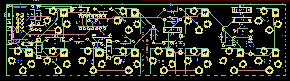
Turns out the trim POT was right hand drawn on the PCB, just not when I laid it in the schematic.
And the caps became one as there was only the +12V rail. that also worked out ok.
There was actually plenty of space but I put it under the IC, if it does not fit there is no problem with it being on the flip side of the board.

Need to tidy up all the references and values.
Sent to JLC…
Any reason you didn’t pour/fill the GND net? Almost every component has a connection to it.