They were unfilled for manual revisions and left out for clarity in the picture. they were filled again. you can just make out the wiggly line of the fill area.
But if you have a ground fill you don’t need separate traces to ground pins.
yeah, that did dawn on me over the weekend as I was finishing off… I think I did it by accident at one point and undid it.
Old dog, new tricks kind of thing. ( although it’s only 4 months since I started learning…)
Will have a play.
Do you use the automatic router?
Cheers
Rob
Does the KiCad autorouter skip routing the ground net if you have a fill? (routers I’m used to tend to route everything to make sure everything has a route, and then do the fill on top of that)
KiCad does not seem to have an official built in AR. I am using standalone “freeRouting” which works well enough.
But I have just done a re-route of my original from a couple of months back VCO with the zones unfilled and yes it takes them into account and has no un-needed tracks.
4 months ago I would not even know about fills… Every day’s a school day! Except for my kids who are at home all the time!
New trick learend 
Rob
Always heard about ground planes growing up. They turn up as important in many an application.
Though for most of my life I’ve pictured a thick bar of metal stuck in the earth with wires attached. (Did a bit of CB radio in my yout).
Learned a while a go that earth and ground are two very different things.
Learned some easyeda recently and saw my first ground plane proper! “That’s useful,” says I .
In the UK
“”“We have your item at Atherstone RDC and it’s on its way.”""
Had this built a few days. Seems to work but it’s difficult to get a decent waveform on my 25 year old Leader Scope.
Hey there. How did this work out in the end? I’m looking for a gate to trigger for a gate only sequencer. 8 individual outs each of which need G to T, so if yours worked all fine it’ll do me very nicely ![]()
Have you tried this, it uses a 4050 so 2 of them can convert 12 gates to trigs…

From memory it worked well enough, never actual needed it in the end so it’s not been tried in anger.
Cheers
Rob
Thanks. I’ll breadboard it, along with craigyb’s and see how I get on.
oo! looks interesting. I’ll investigate this further…
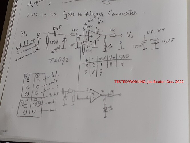
Here’s another one:
Although the schematic says TL072 I ended up using a TL074 and made 4 of them in one module. The lower opamp shows a 2nd stage, sharing the comparator’s threshold voltage resistors at the inverting input with the top opamp. The rest of 4 can be implemented in a similar fashion.
The jack should connect the input to GND if no patch cable is connected.
Lovely! Plenty to play with now…
