It appears the board is about 98 mm wide:
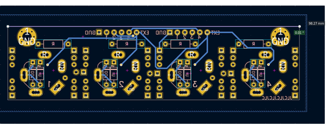
and the outer LED footprints are overhanging the edge. If so I suggest it should be made shorter. Per Kosmo Specification a width no greater than 96 mm is recommended. You don’t want to be bumping adjacent modules. I get that you wanted multiple options for LED placement but 19 footprints is I think excessive. I’d get rid of the outer ones at least.
For Kosmo I always use 5 mm LEDs so I’d reduce or eliminate the 3 mm footprints, replacing some with 5 mm. But that of course is a matter of taste.
Better would be upstream end of LED series resistor to upstream end of output jack series resistor. 98% of the time that’s how you’d do indicator LEDs for outputs. For inputs you’d want some sort of buffer or driver circuit for the LED so you’d need a separate connection from the main board for that.
You could fit series resistors for both LED and output on the board above the jacks. If you use smaller resistor footprints (for 1/8 W or small 1/4 W resistors, or for standing resistors) they’ll fit even more easily.
My inclination would be to get rid of the diode footprints entirely. I use series diodes with jacks rarely enough that I wouldn’t want to have to fill in a jumper to not use one. Besides, a series diode really should have a pulldown resistor between it and the jack for output, or on the other side of the diode for input, and you don’t really have room to add those resistor footprints.