Hi…I am trying in KiCad to create a schematic for a buffered mult. The original schematic that I am taking this from is by Morrocco Dave here who based it off of a MFOS design.
There are 2 changes I was trying to make to his schematic:
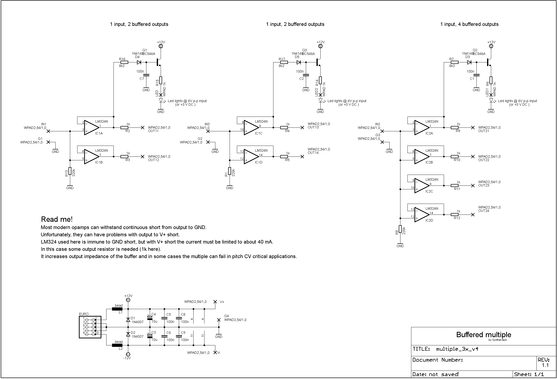
I wanted to add an LED to the input so I visually knew if the input was receiving a signal.
I changed the power section to add in diodes, caps, etc… because isn’t is supposed to have this protection? I saw this particular schematic on another buffered multiple here.
Below is my schematic. Pretty sure there are errors here. Can someone look it over and tell me please any changes I need to make to this?
The LED shouldn’t be in series with the output.
It should go from the opamp’s output to ground thru a limiting resistor (value depends on the LED and the brightness you want, usually somewhere between 1K and 10K)
They’re for power reversal protection. If +12 V is really +12 V then the top diode won’t conduct, but if it’s actually -12 V the rail will get shorted to ground, hopefully blowing out the 10R resistor before any other damage is done.
That’s one approach, not my favorite but not terrible; see Typical module power circuit for discussion of different options.
100R output resistors and no resistor to ground on input is better for preserving 1V/oct CVs. Another option is to put the output resistors before the feedback connection; that gives you no voltage drop even with 1k resistors.
If this is for a PCB design, you’ll want to use different labels on the left and right. E.g. IN1_B for the op amp input and the one on the left pin header and IN1_P for the jack and the right pin header. Otherwise the software will want to connect all of them together.
If it’s for a stripboard or other non-silicon-idiot-designed option, presumably you’ll know better than to do that.
@eric is option #1 or option #2 how I should do the LED on the input? Or are neither correct? @analogoutput is that what you meant by putting the resistors before the feedback connection? I guess technically it’s in the middle of the connection.
Can you guys take another look at this and tell me if this looks correct please?
@Dud thanks for the drawing. I plan to implement that switch you drew. I just haven’t drawn up the other outputs yet in kiCad so that’s why it’s not on this version of the schematic.
I think you can keep the 100ohm resistor like in the first schem (the @analogoutput proposal was if you changed with a 1K that you had to move it)
and for the led, not in serie, #2 is better
Then output = input voltage regardless of what load you connect. (There can be drawbacks to doing it this way so some like to use it only when preserving V/oct CV is needed.)


