Audio jacks need to be connected to PCB ground. If you’re doing that by some means other than the Molex wire, then I don’t think you need the Molex wire.
2 Likes
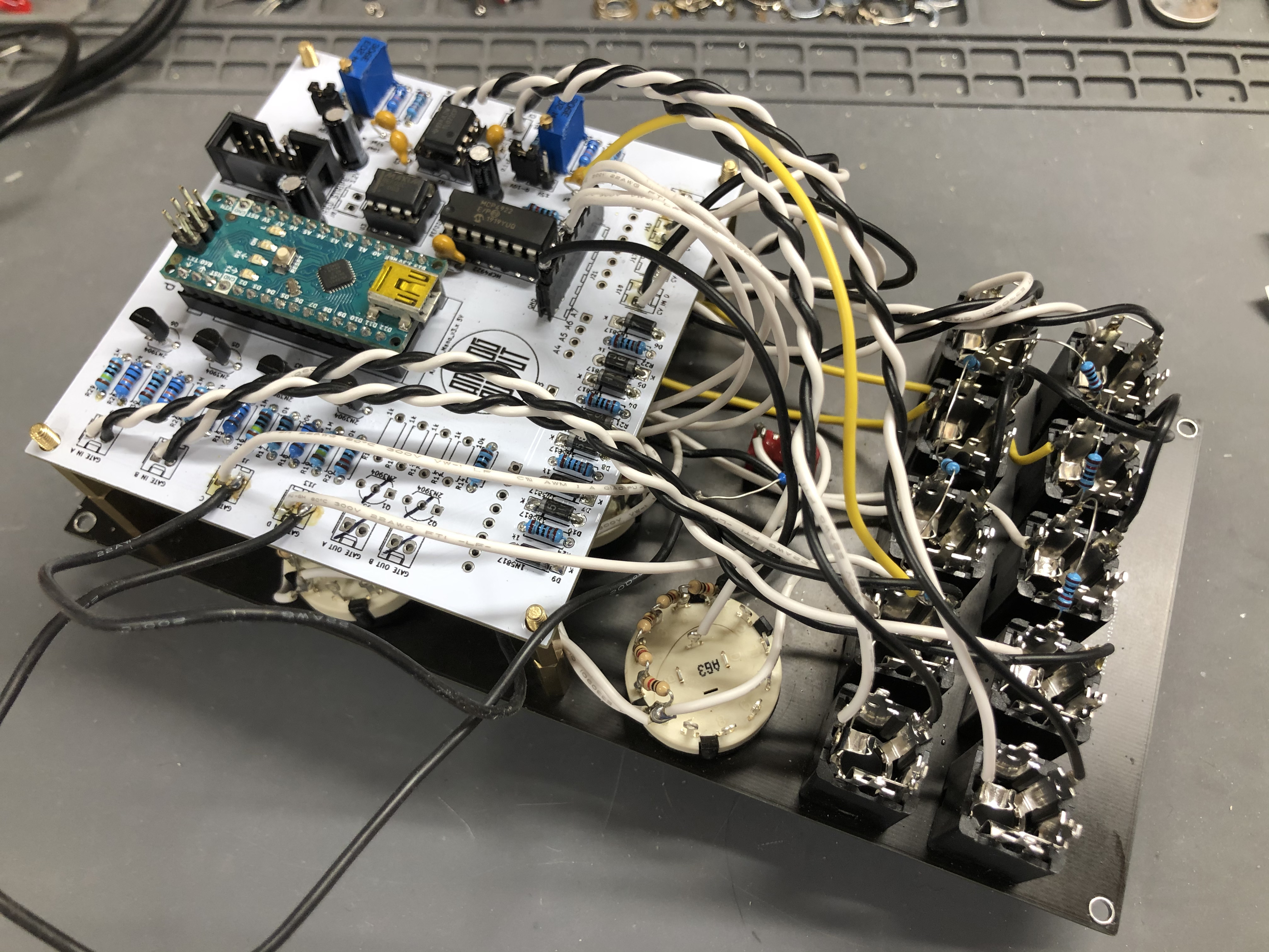
Alrighty. Today’s the day. I’m going to go through the schematics component by component to see what I did wrong. I think the arduino is ready, but I’m not getting anything out of it. I have all of my other Analog Output modules functioning and I really want to get this one working.
Might as well livestream this painful exercise:

3 Likes
Okay. I gave this thing my best shot today with no luck. I did find I had soldered some things in the wrong place on the molex 8 pin connector (J116) like a dunce. After that, I reflashed multiple arduinos, swapped all the ICs. I double checked all the bits on the schematic. I double checked the build instructions. I compared to available photos. At this point, I don’t know what to do and could really use some advice.
Areas I’m not so sure about:
- the resistor chain on the jacks before the VCC
- some of the wires connected to the toggle switches and rotary switches


2 Likes
I am currently trying to get mine working as well!
1 Like
I don’t see any mistakes although of course pictures are no substitute for looking at the actual thing.
Not sure if you’ve tried this but if you run with USB connected (disconnect the regular power, the output op amp won’t work but that’s OK) you can turn on DEBUG in the sketch and see what messages show up on the serial monitor, that might help. Of course you can also edit the code to add or remove debug prints yourself.
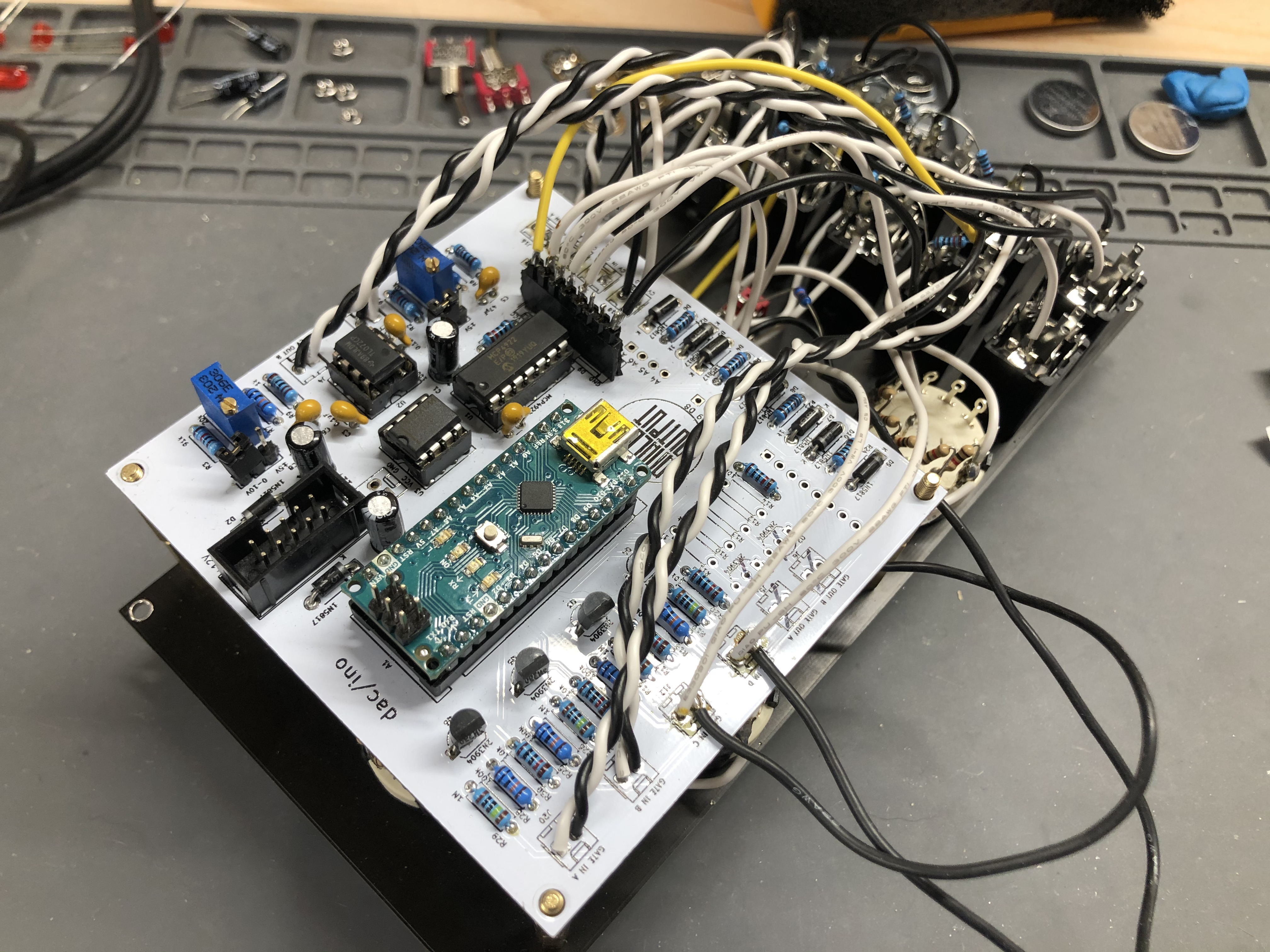
How are the resistors on the jacks connected? Should be:
- 10k resistors to CV2, Quantize, and Trigger tip normal pins. Other ends of resistors to VCC pin on 8 pin Molex connector.
(So each of these 6 jacks should have a 10k resistor from tip normal to VCC.)
1 Like
I changed this and, progress! That did the trick for the bottom row of jacks. The top row still isn’t giving me output. Double checking the schematic in that area. Thank you!
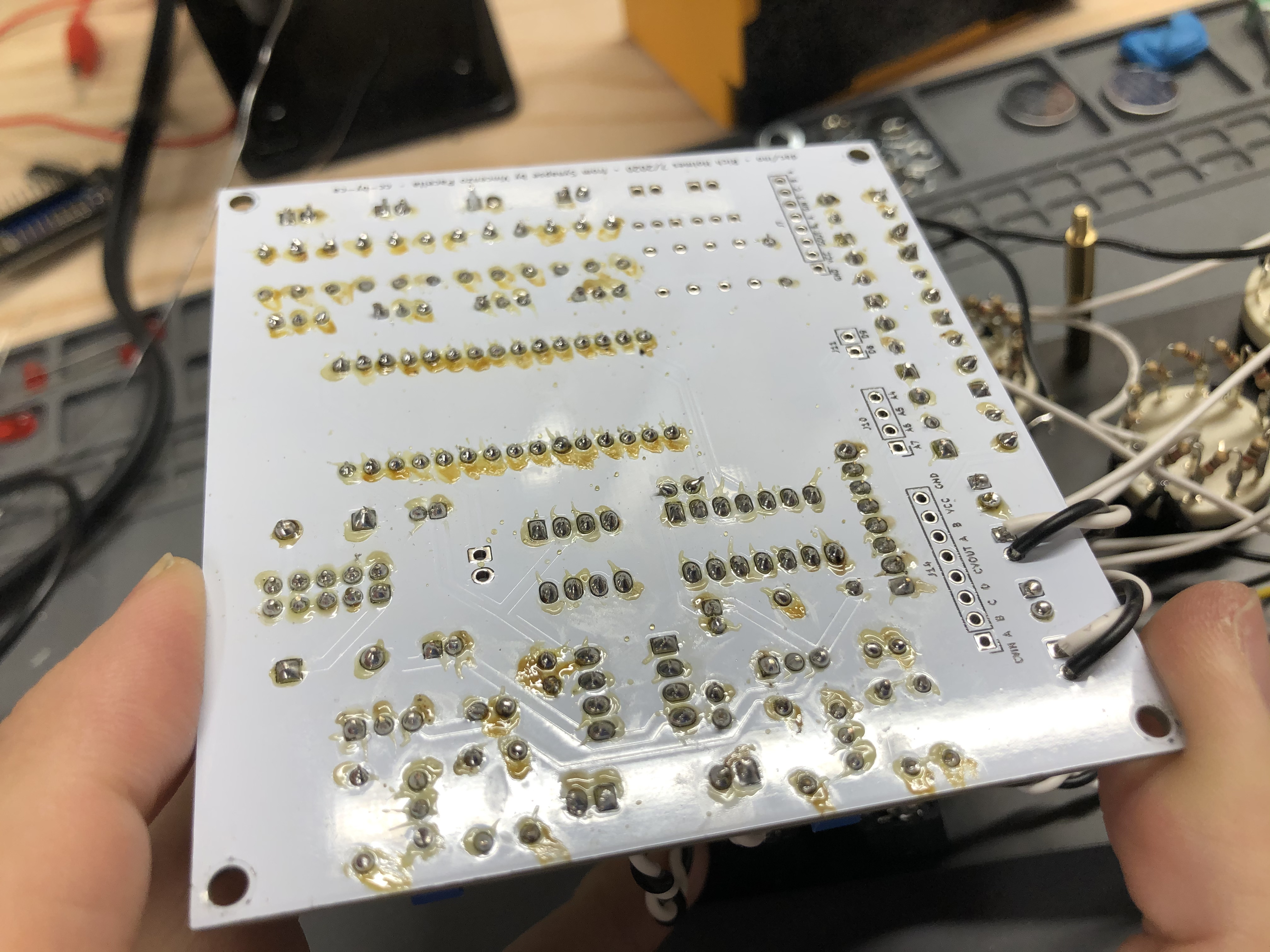
it’s not very easy to see in the photo, but you’re sure there is no short between GND and jack wire here

1 Like
I double checked and cleaned those up. No short. Nice catch, though!
2 Likes
Update: Turned on debug/serial. I get print statements for Unit 2: CV1, CV2, Trigger, Scale, Bank. I do NOT get any for Unit 1.
Here are a few lines:
Quantizer 1 CV1 in = 730 bank 0 scale 0 quantize 1 CV2 in = 1836 CV out = 2553
Quantizer 1 CV1 in = 278 bank 0 scale 0 quantize 1 CV2 in = 1836 CV out = 2109
Quantizer 1 CV1 in = 0 bank 0 scale 0 quantize 1 CV2 in = 1836 CV out = 1836
I’m guessing Unit 1 = Quantizer 0 and Unit 2 = Quantizer 1.
From the dac/ino build notes:
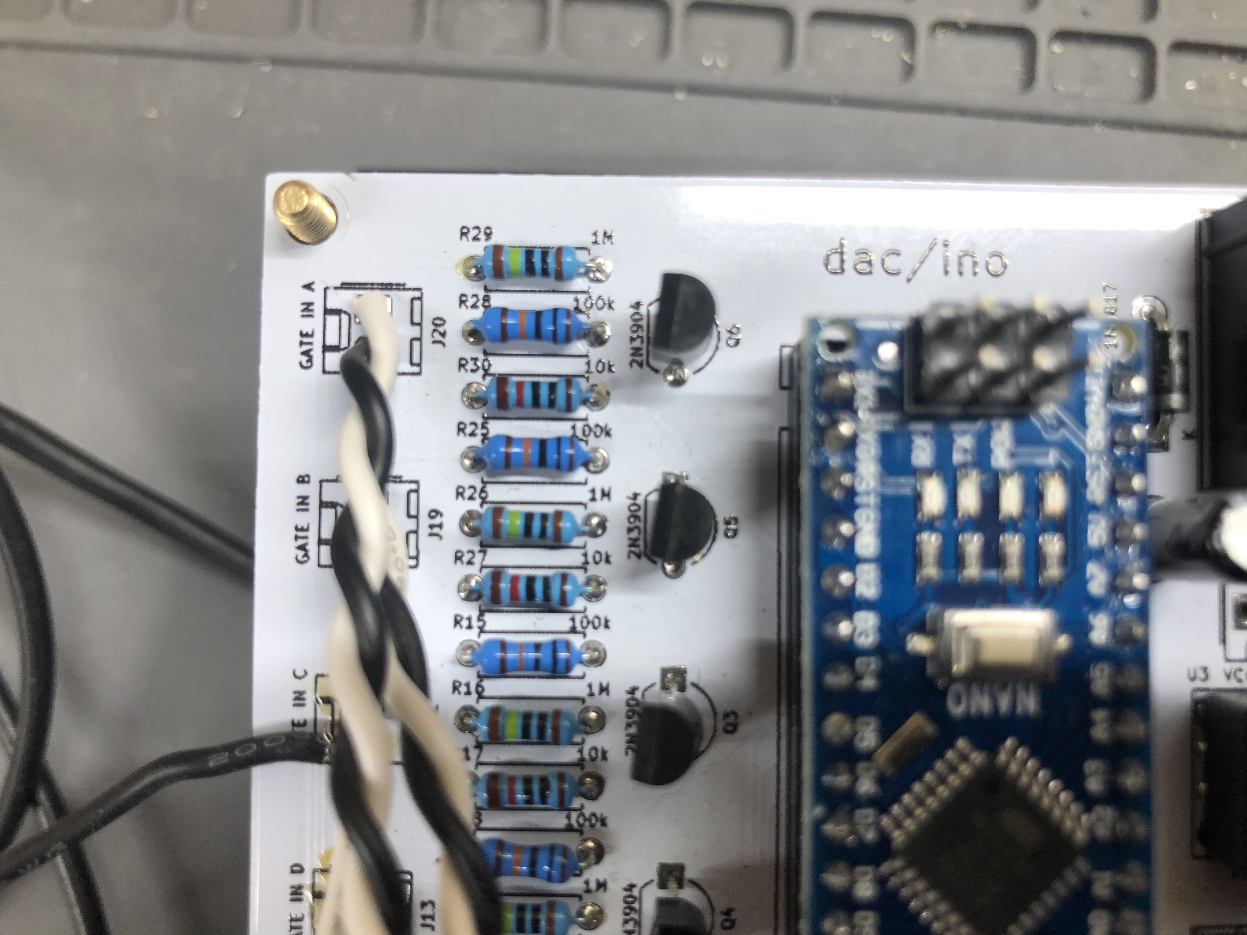
Silkscreen error
In version 1.3, the silkscreened reference numbers R28 and R29 are reversed. R29 is the 1M between R28 and R30. Fixed in version 1.31.
That’s badly worded, the reference numbers and values both are reversed. The corrected version looks like this:

So indeed you should switch those two resistors.
4 Likes
THAT DID THE TRICK! And yeah I was combing through every bit of documentation and saw that. Thank you for your help. This will be in my case on the next stream.
7 Likes
Whisky tiiiime! Cant wait to see it working =D GJ!
4 Likes
Seriously, thank you all for your help. This one was a tricky one, but stoked to see it working.
6 Likes
Psh dont thank me lol. in hacking terms id say we bashed it with our dual-core CPU(aka brains).
It was fun trouble shooting with you and fred. Knew you’d get it eventually.
BTW the Talisker is doing me some good. My typing has improved? =D
1 Like


6 Likes
I think this afternoon I will remove the positivizer (maybe make it a module later) because by testing it, I don’t really think of using the Quantizer with LFOs which just makes a scale that goes up and down not very interesting for my taste , and the 8 step arduino seuencer has 2 CV outputs and I could not use the 2nd with the quantizer in my patch (with 2 : interresting possibility to make some double notes synchronized and tuned: mini chords).
Other thing, i tested with different white noise source for S&H, and that’s don’t work well, that’s make a “crunch” sound on each triggering 
that’s not what interested me in this module because I already have an S&H but it’s still annoying.
1 Like
You have to use a short enough trigger for that. It samples the input as long as the trigger input is high, so if that’s a gate more than a few tens of ms long it’ll try to quantize several random values during that time. If you run your clock through a gate-to-trigger that should fix it. “Trigger” might be the wrong label for that input, it’s a sample gate really. Or of course you can just use your other S&H, and quantize the output of that.
I tested it with the “Big button” trigger sequencer, isn’t that a good signal for that?
I have no idea… But it should work without “crunching” if the input is narrow enough. Unless there’s something else going on I don’t understand. It works for me. Been a while but I think I used the trigger out from the Gate Grinder.
See

at 4:26
1 Like