Not all nanos may be the same, but the 78m05 regulator on the original nano could easily handle +15V. Check carefully to make sure you supply your power to the correct pin on the board. It may be wise to supply some sort of heat sink to the onboard voltage regulator, as it has to dissipate twice as much power as the rest of the board if you’re feeding it on +15V.
Well! Getting nice 5v out of the arduino now. Powered the switches and buttons with the regulator, thinking it would put some load of the arduino. putting around 7v (out of a 9v battery) into the arduino.
Still getting 3.8v out of the mixed gate out. Getting about 4.2 out of the single gates… But my ms-20 still isn’t triggering… Which I just don’t understand… I tried some other voltages which it seems to go off. I’m confused… I think it has something to do with how the ms20 works? Surely it doesnt NEED 5v does it? Cause it triggers off of white noise… I noticed it triggers when the voltage drops again… Weird. but ok… The sequencer… Looks to be working fine though…
Just tried it. The answer is no. If it breaks… I´ll report back…
I’d like to make a suggestion: Try the orthogonal approach ( learned this today in a machine learning specialization course, and didn’t expect to be able to use it the same day! ): I mean: try every part on its own. So check the voltage of the output independent of the ms-20. Then try them combined and check whether the voltage remains the same or does it drop to a lower value because of some unexpected load?
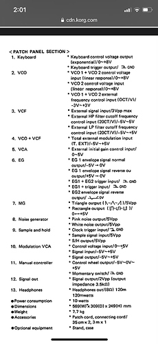
Are you trying to use the keyboard gate of the 8-step for triggering the envelope on the ms20?
The function of the diodes is to make scanning the potentiometers and buttons via a bus-kinda-structure possible. If the diodes were not there then trying to read one potentiometer would not be possible, they would in principle all be measured since their center points would then all be connected in parallel. The diodes prevent this from happening.
I’m talking about the diodes in series with the inputs. I agree the other diodes are needed.
They’re there to isolate whatever’s plugged in from the switches, right? Not all outputs are happy to be connected directly to +5 V, especially not if they’re trying to pull the signal down to 0 V.
Oh right. Missed that bit.
Ah, that’s a good point. Thanks. [makes note to self to keep those diodes in after all when I build mine]
Well I was trying to connect it to the trig input of the keyboard. Which apparently is also on the panel… So does this mean it triggers when connected to ground? Does this equal 0v? So then this means it just never gets 0v? (which I already measured, it doesn’t do) That would kinda make sense… Pretty annoying too… Because my keystep also triggers, when you release a key… (I could use the midi, but that’s no fun)
One more fix…in the code. Version online has buttons 7 and 8 swapped. Swap 20 and 21 in code to get it fixed!
Along with a couple changes to the wiring:
I’m screwing mine down hallelujah
Hmm yeah good question. Not sure what that means exactly maybe saying it triggers on a falling edge? Btw I left my voltage reg and am still hooked up to VIN
Optional, but changing one of the clock inputs to a switch to toggle between the two directions is nice…
Oh my! And I thought I messed up the wiring! 
And agree about the switch! Going to put that in as well!
As to the ms20… Looked at the schematic. There’s a diode there… So no voltage can actually go in. It makes a gate, when either closing the circuit through a button/switch. Like on the actual ms20. Or by grounding it to the thing that’s plugged in…
So I measured resistance of my keystep… And there’s a brief moment were resistance goes, and I’m assuming it quickly grounds.
Tested the theory by hooking up a jack to the ms20 and connected the sleeve and tip with a wire. Surely, every time they touch, the gate opens…
So If I understand the lfo of tthe ms-20… There are resistors to ground at the output. So everytime the voltage drops… Current goes to ground… So it triggers
The only thing I don’t understand is why the pink noise actually gates it, while the white noise doesn’t…
Now I’m going to think about… How I could make it happen with this sequencer…
Just guessing, but I think it’s likely due to the fact that pink noise is biased towards lower frequencies whereas white noise is randomly (uniformly) distributed through the audible spectrum.
The result is that you get different energy distributions across the spectrum, and after smoothing the pink noise will present a higher voltage at the gate.
Like, but I think when I do mine I’ll find space for both jacks and a DPDT switch to exchange their roles
I’m trying to figure out the benefit in this case because you can only have one direction at a time. So your switch would have to swap the roles and shut one off?


