i think the same ![]()
Any chance of a stripboard layout for this?
look on Sam website 
There’s a single PT2399 stripboard at https://www.lookmumnocomputer.com/projects#/2399-triple-splashback. The triple PT2399 is probably too nuts for stripboard but that’s a starting point anyway.
If you can read schematics, you could basically build three copies of that and add the glue on a fourth board, but that’ll take some effort.
Sweet! Thanks! I had checked the page when it was first posted. Don’t think it was up at that point. My main concern is voltage control. How could I add that to this circuit?
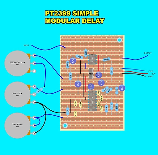
here is a simplified single delay i have drawn based on the above circuit, HI RES. it has no cv control as that makes it rather more technical. however you could pop in a vactrol to do that job. put a vactrol over from pin 1 to pin 3 of the delay time knob and see what happens.
Saw that. But I’d like to do it without a vactrol. Been seeing this around. May give it a shot.

i know this schem but never tested, maybe try on a breadboard ?
or a vactrol that seems more simple for me
hey dud yep its easy. the above circuit or you can look at how the splashback does it, as thats tested. check the cv control aspect of the circuit you only need it up to the first 2n3904
Amazing! Thanks for that link - way better than trial and error parallel calculations!
Hey, wait – *the* nervous squirrel? Huge fan!  (& welcome!)
Ha ha, thank you! Just Nervous Squirrel no. 248 actually…
Oh, there’s like 250 of you? That might explain the scale of some of the builds I’ve seen on your site 
yes me too I follow your work for a while, excellent !
Just wondering if anyone has actually built the simple delay from the stripboard layout? I built it. Seems to power up and run dry audio signal fine, but zero delay. Double and triple checked it over. Don’t see anything out of place.
to be shure that’s not an error on stripboard( It could happen)
maybe check the big schematic,
compared the way with one part of the 3 delay
As I understand it the stripboard version should be mostly the same as the datasheet version, so there’s limited opportunities for there to be an error in the circuit.
Have you checked the layout for discrepancies with Sam’s circuit diagram?
All seems to check out. Must be something stupid I’ve done…again. Lol. When I get a chance, i’ll go over it with an audio probe.


