For the resistor value which 51k was recommended on the datasheet which alternative values bring the outputs closest to equal? I found it confusing as to whether 20k would match the outputs. In fact the closest I have to 20k is 22k as I bought many resistors and that’s what would be the value included. Would going higher than 22k bring the outputs closer to equal? I would prefer matching the pulse output to ramp/sawtooth output but maybe even a compromise between triangle output and ramp/sawtooth output.
Thanks for the Arduino help guys, have it loaded. 3 waveforms working, display lit.
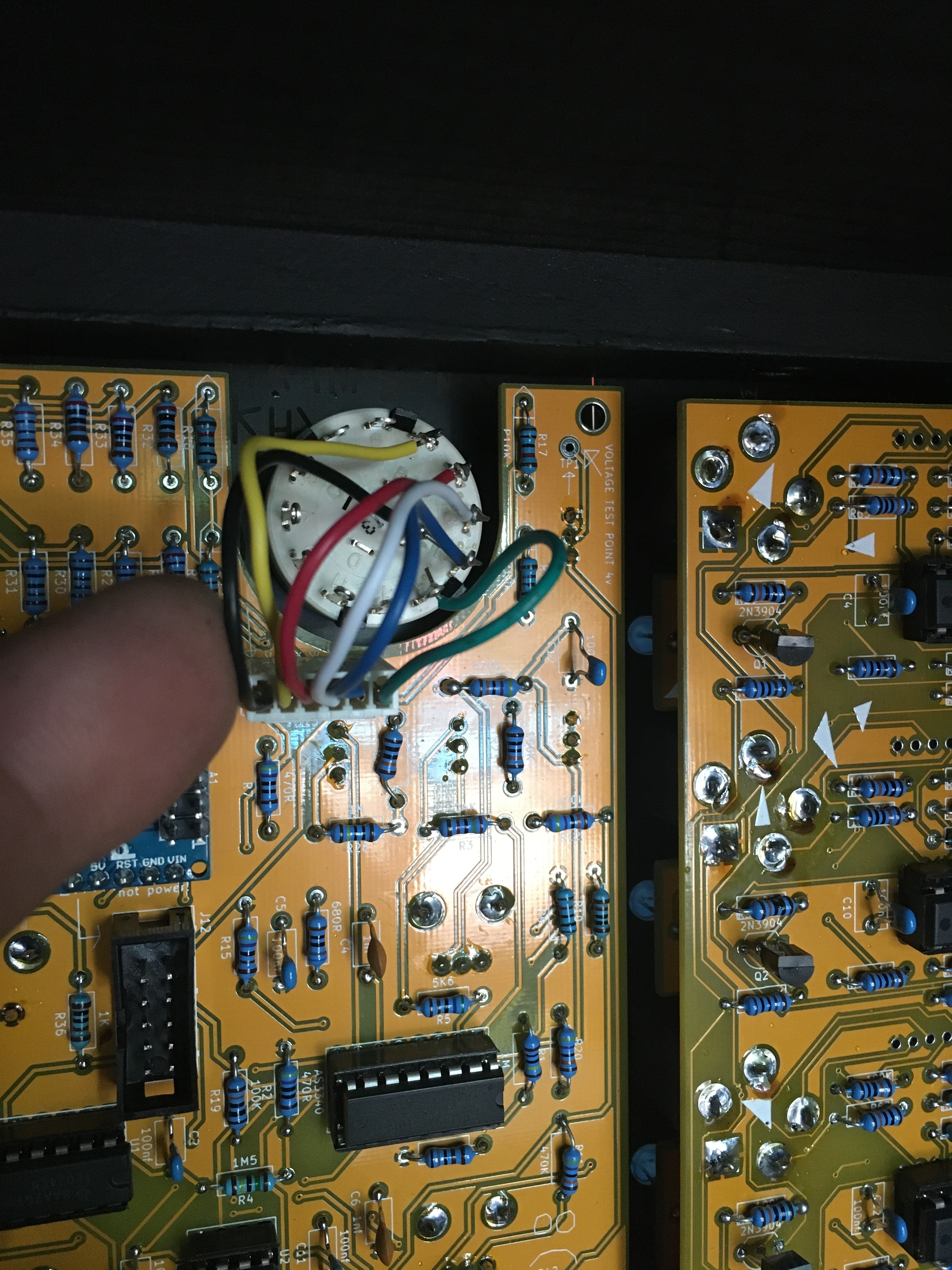
Nothing happening with the octave switch or tuning knob. Suspect a missing ground connection, anyway from tp1 to ground, no voltage. What am I missing?
Is R42 connected to the +12V bus? Are U4 and RV3 connected to ground? Is there ~4.1V on the RV3/U4 node? Does turning the screw on RV3 change anything at TP1? Is there a short to ground at TP1?
Well, apart from calibration…I think mine is done…
I had 3 Issues.
one LED had a leg unsoldered… Easy Fix.
The tuner display gave out seemingly random junk, I was using the revised code. Even the test mode was garbage., ( Found a setting for Common Cathode/Anode and swapped that Sorted…
My rotary switch was mechanicaly not located, I drilled a hole for the locating pin and had to replace the switch as I cat cut the locating pin off the last one.
I now had 1 major issue…
No waveforms … I could here the amp clicking as I jacked in so that sugested the opamp was ok. I breifely got something out of the PWM…
Turned out I had trimmed the rotary switch to the wrong end of it’srange and NO octaves were being selected… Sorted that…
And Hey preseto everything looks GOOD
Since that is probably the most complex of the modules I am fairly happy the rest will work.
Does the 7-segment display work, but not the LEDs? They’re driven by the Arduino’s GPIO pins, just like the display segments. Triple-check that you haven’t mounted them backwards.
Hi All,
My two 1222 tuner VCOs have arrived, and I’m having some difficulties - chief among them being that the code does not run on an Arduino Nano Every (a bit of info that exists on the project page, but isn’t too obvious…). Anyway, it looks like I either get to buy more Arduinos, or adapt the code. Out of curiosity, has anyone run into this issue and/or come up with a fork that works on the Every? I appreciate anything to point me in the right direction, since a lot of this code stuff is way over my head.
Cheers,
-Wes
I ( and everybody I guess with a working one ) will be on a stock Nano, whilst the Every is similar it has a host of technical differences. And for the cost of a Nano, it’s not worth loosing sleep trying to re-think it.
The code does not run, or the code does not compile? (they use a newer version of the core Arduino libraries for the Every, and some legacy code won’t compile out of the box, see e.g. the digitalWrite issue in this thread.)
Finally have the 3 VCO’s working as they should, many thanks Fredrik!
Connected Keystep to 1v/ocv with pitch output, didn’t behave as I thought.
Only cable I had was a stereo minijack, could that be the issue?
After building, work in progress, several modules, I realise I have no idea how they connect or should sound.
Hey all,
I am building a couple of these bad boys and I discovered a slight screen print error. The attenuated control voltage (FM) leads to the solder point labeled CV instead of the solder point labeled FM. It only matters if you are doing outboard wiring, which is true in my case. Sam, you may want to swap the labels on version 2!
Best,
-Wes
My 1222 started going crazy today, bouncing all over the place for some reason. When I touch the wire going to the octave switch it really sounds nuts. Any ideas what it could be? It worked just fine last night.
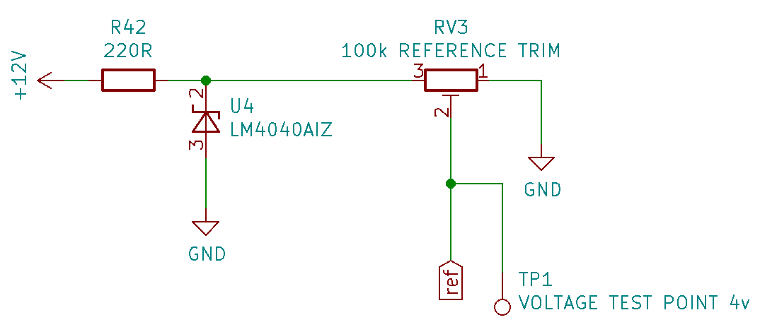
 but agree short somewhere around there is likely. Also double-check that you put in the LM4040AIZ the right way.
 … I could here the amp clicking as I jacked in so that sugested the opamp was ok. I breifely got something out of the PWM…