Update: I build this thing and it kinda sucks.
3 Likes
Shield it and ground the £**k out of everything usually works
It gives a little bit of boost, which makes the triangle out of the LMNC VCO a bit more usable, but it isn’t enough to boost line to synth level so I can’t use my volcas. I should have built the microphonie instead…
2 Likes
I also tested this (from Berlim Crisis) and found it a bit lazy for this purpose.
I got a good result with this one:

Junito’s Nigh Infinite Gain Amp
You can get a lot of gain through this.
2 Likes
Three pots for an amp?! What do they do? I like the potential though…
2 Likes
It’s a strange design. Input impedance is only 10k instead of the 100k usual for synth modules. There’s a 1k series resistor before the last op amp and none after, I don’t understand what it’s for.
The pot on the left attenuates the input signal, so the “gain” at the + input ranges from 0 to 1. The middle pot varies the gain of the first stage from 2 up to “nigh infinite” (which means of course all but the tiniest signals get clipped if it’s cranked that high). And then the third pot just attenuates the first stage output, so the final gain is from 0 to “nigh infinite”.
Between either the first and second or the second and third pots you get from 0 to infinite gain, but the first pot attenuates before amplifying while the third attenuates after amplifying, so you get more clipping by using the third pot than the first.
It seems to me (checking with simulation) the left 10k fixed resistor in the feedback path doesn’t do anything. It could be left out. Then you’re left with an ordinary non inverting amp, followed by a voltage follower, with attenuators everywhere.
If all you’re trying to do is boost without clipping, you can do it more simply than this.
3 Likes
Yes, the circuit is very strange.
Good to understand it better through your analysis since the author doesn’t give much information other than was described on the instagram link.
I believe he did this as an experiment.
In my case I was trying to introduce a low gain signal to the audio input of my MS-20 Filter.
I built the circuit on breadboard with a NE5532 adding a 1k resistor to the output of last opamp. I also replaced the first pot with a 10K resistor but for sure a 100k resistor makes a lot more sense.
The result is that I got a very big boost, adjusting the two remaining pots I was able to send smooth or clipping tones with a high gain. At some point it became bizarre.
Eventually I abandoned the idea and just used a simple mixer to boost the signal.
2 Likes
Been meaning to get around to this one for a while, and it’s finally done. I’ll try to do a video or something eventually. I really like it:

This is a quadruple independent slew rate limiter, that slews up to 4 signals with the same slew time, using a single 4 gang pot. Is is based on YuSynth’s single slew rate limiter:
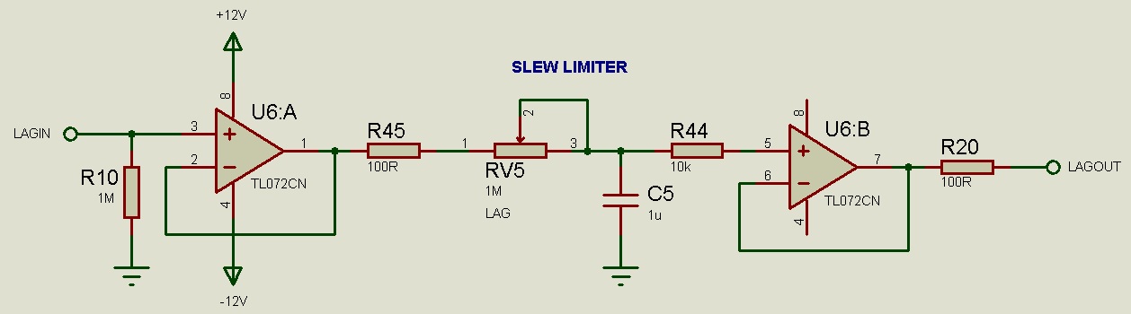
(that’s the schematic, I can’t seem to find the full project page right now). This is the pot I used:
You might be asking yourself, “Ok, but why?”
The main signal path in my synth uses a stack of 4 oscillators, two on high note priority, and two on low note priority, making it easy to play all in unison, or to make duophonic chords. By doing it this way (instead of a single slew rate limiter with a buffered multiple output), each of my slewed control voltage signals can have different destinations.
Some quirks and comments:
- There aren’t a ton of choices for 4 gang pots for through-hole use, which is how I landed on a 50k C taper. Feel free to use what ever you can get your hands on. The C taper feels fine. I suspect B would be better, and A might be kinda wonky. Never know till you try.
- As always, bigger caps or higher pot resistance value = more slew time. I chose mine based on experimentation. I didn’t want the times to be insanely long.
- I got rid of the pull down resistors since my unit is literally hard wired into my midi to CV converter, so it will never float. You might wanna add input pulldowns if that’s not the case for you.
- The caps aren’t matched perfectly, which means there are slight variations in the slew time for each channel. I kinda like that. You might not.
- At one point I accidentally connected the ground plane to a 5v trigger signal instead of ground. This produced some interesting unintentional effects. When I pressed a new key, the signal would start out 5 octaves too high and zoom to the target note at the slew speed. When released, the trigger signal would disappear, and the note would go 5 octaves too low and again, zoom over to the target note at the slew rate as the VCA decay rang out. I definitely corrected this, but I thought it was interesting and maybe some day I’ll experiment with manipulating the grounded legs of the capacitors to achieve weird pitch envelopes.
Here are some photos of the build. I eventually made two, but the second one uses only 2 channels instead of all 4.
Login • Instagram
Hope this helps someone, but it’s still worth it if nobody ever builds one but me XD
-Wes
5 Likes
Another long overdue project I powered through this week - adding a dedicated “filtered noise” knob to all of my filters.

This noise generator is pink-ish, but probably not perfectly pink. I set the gain insanely high because I wanted to be able to push my filters hard and do cool resonant sweeps, or make it so noisy it’s almost drowning out the oscillators. Adjust the gain resistors to your personal taste. You can also adjust pretty much any of the resistors and caps in the filter portion of this circuit based on what you have laying around, and personal taste. Especially the caps on B15 and B16. Bigger caps make it darker, smaller caps make it lighter.
This is the schematic I abused:
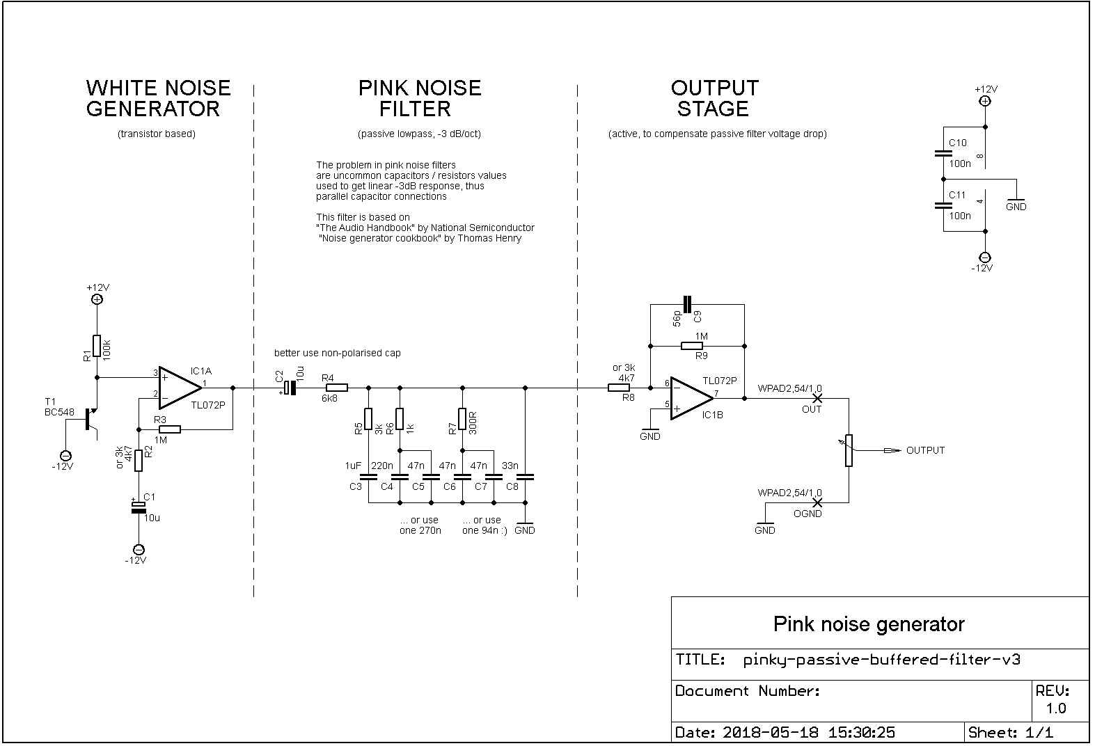
I used the version from the “Audio Handbook”
This was a fun project because it’s really easy to personalize your sound while maintaining the same topology. Just breadboard this bad boy, plug it into your filter, and start farting around until you get a sound you connect with.
Here’s a photo of 2 of them:
https://www.instagram.com/p/CeDX8Q_ryD0/
I need to make some recordings at some point - I never get around to that part >.<
8 Likes
Here is the strip board for my version of the 2700 Twin-T drums that I used in my drummer synth. I am quite happy I found this larger size strip board on Amazon in the US. I can’t really find boards this big anywhere.


8 Likes

Here is a layout for XQP’s Colourupter Compressor. I used 3mm red led, it needs very hot signal to work with higher treshold leds. It has the charasteristic meaty optical compressor sound. Clipping the signal before the compressor makes it activate easier as it uses AC signal instead of DC in sideband.

9 Likes
Nice. Any chance you can show us what it sounds like before/after ? ![]()
1 Like
Here is a comparison of bass sound with and without it.
The attack is quite slow (full compression at around 20ms) and boosts transients nicely.
As you can see the compression has high ratio (or low treshold idk).

5 Likes
Looks great for drums!
2 Likes
It does work with noise snares well! The decay just has to be a bit longer than usual.
Not sure about hihats as it needs enough of that low end to react as it just uses AC signal in sidechain.

1 Like
Did you just build the board like you’ve got it in the stripboard layout and then tape the led/ldr together?
Yes. I put the circuit in lightproof box but they could as well just be heatshriked/taped together.
2 Likes
These are two stripboards for POLYKIT’s pi pico project. Great way of getting polyphony simply. Build three of the dual oscillator boards and you’ve got 6 in-tune oscillators with saw and square outs being controlled easily by MIDI DIN. Both now verified - will add boards for the envelope generators, VCAs, and filters as I go.


6 Likes
Hi there,
I have just finished building the triple Lfo. It works great. I have added a summing circuit of the 3 Lfo s that can be output through the 3rd Jack by means of a switch. So, you have either 3 separate outputs or 2 individual outputs and one summed output. That summed output results in interesting patterns.
For the moment the three lfos all have the same caps. I would like to make them ranging from slow to medium to fast.
looking at the build pics by ronnberg and Soundbender, they seem to both use bipolair caps. When looking at the original schematics they are refered to as non polair…
At the moment I have used bipolar caps. Since I dont have nF bipolar laying around I would like to change them to ceramic caps.
Can anybody confirm whether that would be ok?
The original schematics can be found on the lovely website of @Dud ’
4 Likes