That’s how I’ve ususally done it…but I learned more about power nets a board or two back and was able to just use PWR_FLAG’s to identify them so it automatically hooked that up behind the scenes. Not sure why it’s not doing that on this one. But I was getting pretty tired last night and didn’t try to think it though - was just trying to get all the components down
I don’t fully understand how that part of the circuit works either. It comes from the dogsnakes noisedrum (which I really like as a hi-hat) and it works…I’m just not clear on why/how.
I think this is the noise generator as discussed elsewhere in this thread. It’s advisable to cut that unused collector leg very short so as to eliminate unwanted RF interference.
I guess now that you have +5V and +12V power nets, kicad just chooses one… by some arcane algorithm…
Did you have both in your previous design(s) where it worked ?
I never trust software… I know why, after all, I’m a software developer
I guess it knows which pin of the IC should be positive and which negative, but by no means can it know which voltage.
I never designed a symbol in kicad, so maybe I’m wrong… what attributes can you set on power pins ?
In the video, his module (Twin T kick) have an Attack select switch, it’s not in the schematic and i really don’t understand his explaination about it.
Some one can help me plz ? what’s he saying ?
He says these diodes are connected to the switch to provide two attack responses but yeah it doesn’t show how…but I imagine the switch would break the path going thru both diodes
As far as I can see it’s just switching between two cap values to give you different lengths of decay…like sso pitch ranges. Or did I miss something?
Edit: yeah I missed that. Im off to sleep
Hi, I made the Twin-T kick Drum on a stripboard, but I have a problem with the trigger input, it only works when I send a negative gate, the craziest thing is that it worked normally last night, I double checked and reflowed all my connections (from the krakenpine schematic and the stripboard layout), it’s driving me crazy and having only a first price multimeter at my disposal I don’t know what to do to debug it since I have no point of comparison.
Do you have any leads, tips or values that I’m supposed to have on certain components?
For example, what voltage am I supposed to have between the 0v line and the different legs of the OP-Amp?
Also I noticed that I have a few millivolts between R1 and GND but it seems normal to me from the schematic
Hi to you, sorry I suck in theory (other here could help you better), I just made a stripboard from the diagram and everything worked on the first try. Check your circuit again, there is bound to be an error somewhere . Maybe show us pictures.
I’m sure that the problem is on my side since it worked briefly, I’m changing all the capacitors, since I can’t test them with a multimeter, here are some pictures.


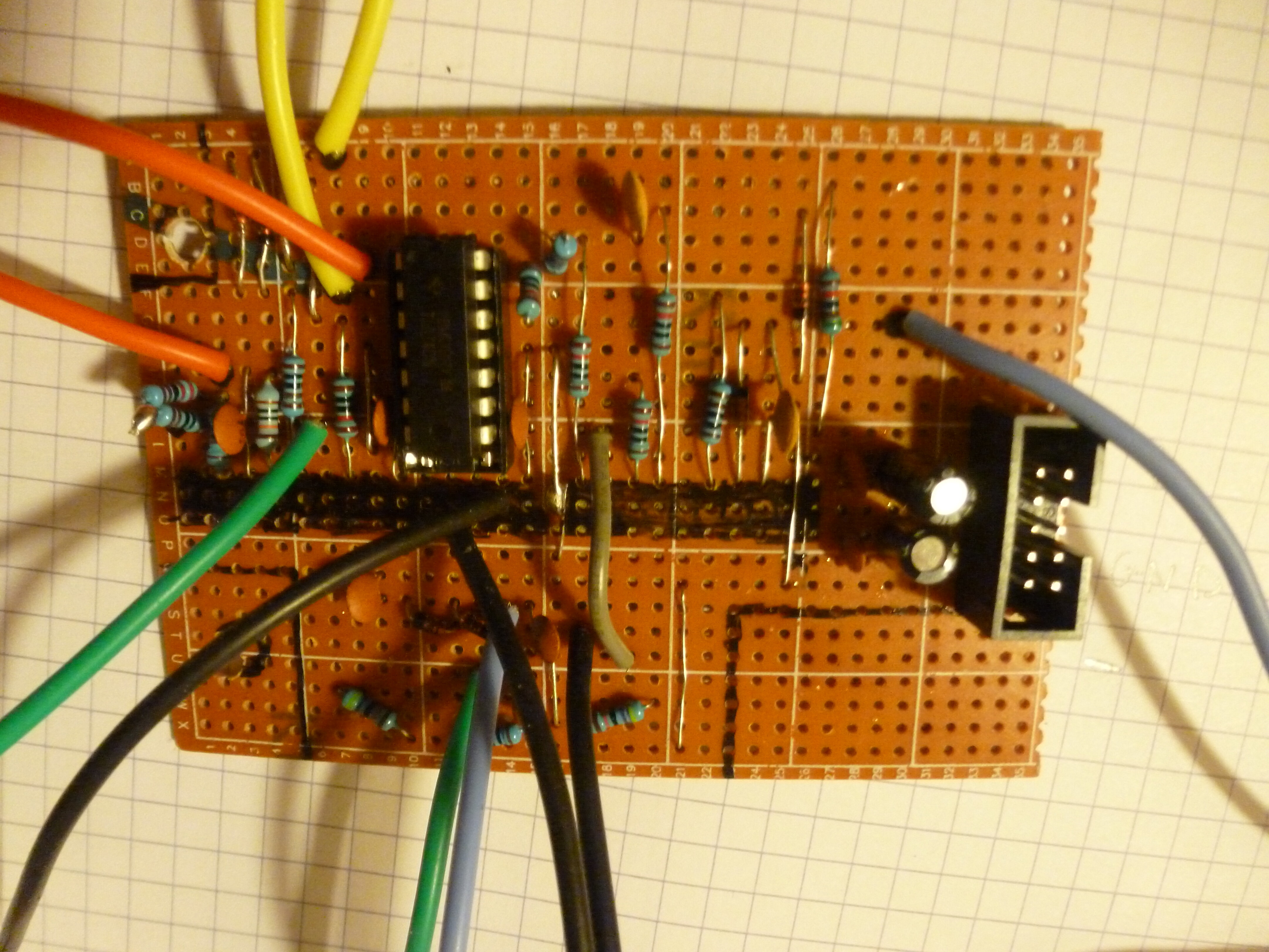


 so i think it’s come from the part i change I will post the modified layout.