Hi there,
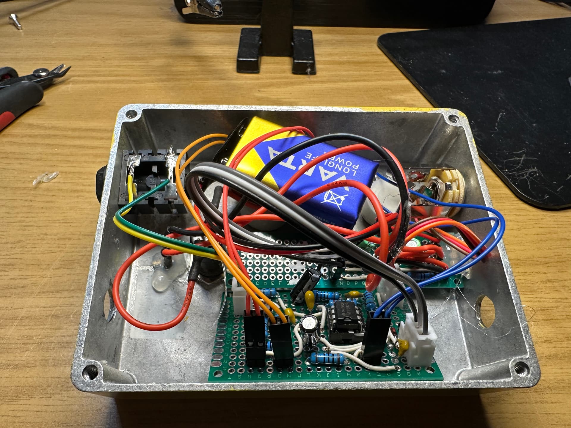
I am having a bit of trouble with an op amp circuit that I have modified a bit and I am not sure if the trouble is caused by my modifications or if I made a mistake in building the prototype.
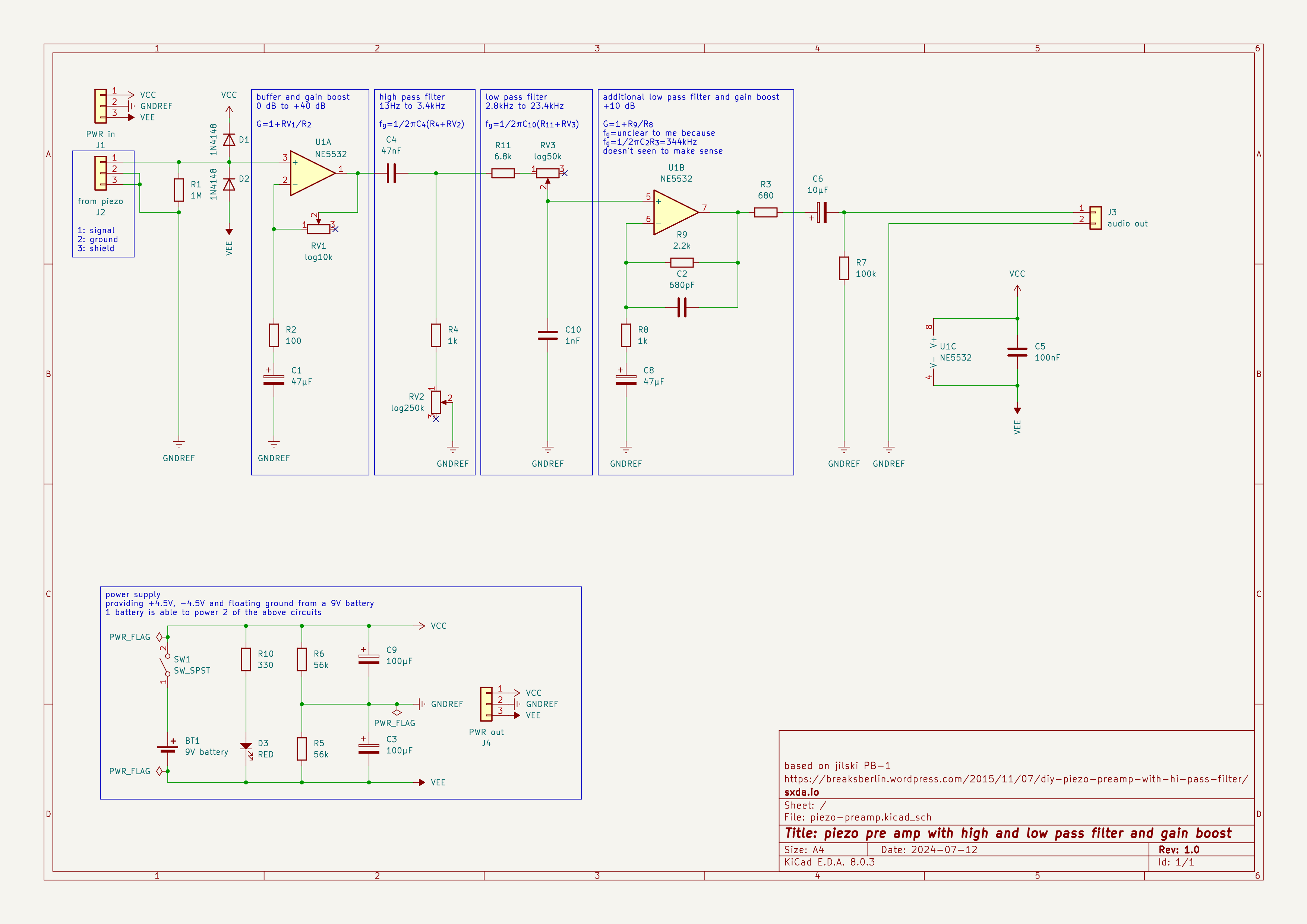
My application is a piezo contact microphone in a noise box. I want to match the impedance for a line in and I want to be able to apply an adjustable high pass and also an adjustable low pass filter.
I have found a promising circuit (DIY piezo preamp with hi-pass filter – breaks.berlin). Unfortunately I didn’t have the 330nF capacitor for the high pass, so I replaced it with a 47nF and adjusted the potentiometer accordingly. The original circuit didn’t have an adjustable low pass filter, but in the blog post jilski said that there was a fixed low pass filter to filter out radio frequencies. Due to my lack of electronics knowledge at the moment I wasn’t able to calculate the cut-off frequency (at least the result didn’t make sense to me). So instead of modifying the existing low pass filter, I added another one before the second stage.
The problem with my prototype is that no matter what kind of noise I make and how I set the filters, all I hear is a single click sound. And the adjustable gain boost doesn’t seem to have any effect either. I checked the prototype by measuring every pin of every net in the circuit (and fixed the error I found).
I would be grateful if someone could take a look at the schematics and tell me if this should work theoretically and the fault is in my prototype, or if the fault is in the circuit design.
The frequency calculation for the additional low pass should actually be 1/2piR9C2 = 106kHz.
My guess is that you’ve connected pin 3 of RV2 to ground, instead of pin 2. In your schematic, pin 3 of each of your pots is left unconnected. You should connect that pin to pin 2 of each of the respective pots.
Other than that, the circuit should work, but that additional low pass circuitry is unnecessary – you already have a low pass, with a much lower cutoff, so you could convert that second op amp to a buffer, by removing R8, R9, C2, and C8, and replacing R9 with a jumper. You shouldn’t need the extra gain – the gain of your first op amp is massive. Sometimes it helps to simplify as far as possible.
Thank you so much! I followed your recommendations and modified the circuit accordingly. It works now. You were also right about the gain boost, even the first one is massive.
At first I thought it was strange to connect pin 2 and 3 of the pot. But after reading and thinking about it a bit, I think it’s clear now: it’s not guaranteed that the wiper is always perfectly connected. In such situations, pin 1 would float. Connecting pin 2 and pin 3 will prevent this and the potentiometer will have maximum resistance in these situations.
Another lesson learned: Build and test the circuit on the breadboard first.