" When in doubt, go bigger. It’s Kosmo format after all. "
yeah this format isn’t intended for the small flat on the coast .
more for the stubby fingered bloke who’s tipped a few and trying to play something on a dark stage .
and in the mean time it takes up half your dam house .
3 Likes
Had my first go at dying SLA resin and printing some knob caps out of it. Not exactly a success but learned quite a bit so not exactly a failure either:

The rook on the the left was printed in the same plain white resin I used as a base. The lion on the right was printed in an “aqua blue” resin from Phrozen which I’ve had GREAT success with on both of my printers. The knobs in the middle - with my dyed version of the white.
What I found interesting is that I had a lot more failures than when I printed in plain grey resin. I was kind of anticipating this due to the extra dye…but I had also found that white tended to need less exposure than grey for the same results so didn’t adjust my exposure times too much from standard grey for this. But the skirts of the knobs failed a lot more than I expected.
I’m not sure if this is exposure or lift speed. The resin was 80ml of elegoo abs like white, with 20ml of siraya tenacious to which I added 15 drops of “Sky blue” epoxy dye and 3 drops of what I assume was saphire blue (I can’t say for sure since the bottle leaked in shipping and obscured the label - but it was the only other blue in the set of dyes I ordered. But when I added it it looked more violet than blue even though the drops in the baggie it came in looked blue…so…yeah.)
They finished prints look pretty similar to how the color looked when I mixed it up. I purposefully wanted to err on the side of caution and go too light rather than too dark to start. Even so it’s lighter than I thought it was going to be. So I’ll try adding some more dye before my next attempt.
As for the damage on the caps. They are very thin…and I can tell that the tenacious is making them less brittle than when I printed them in standard grey. So I’m thinking a slower lift speed AND a bit more exposure will be needed to get better results. I’m guessing this is more that I haven’t printed with the white much and don’t have a good baseline exposure figured out for it yet than due to the addition of the dyes.
So - further experimentation is called for. Just…would rather melt some solder and finish this mixer and a few other things than dig in on that right now 
4 Likes
Did a little bit of cleanup on my LFO last night:

Added a second output so I have Square and Triangle available simultaneously. Added a label for Range and a hole for the LED. Then re-organized things a bit to make it a little more user friendly.
The OC side of me is a bit tweaked off that the Rate knob is at a different height than the Frequency knob on the Avalanche VCO. But…I’m more likely to reprint the VCO plate than adjust that on the LFO even though the LFO doesn’t quite follow the spacing I’ve been adhering to.
FWIW - I’ve been generally spacing things 27mm apart starting from the bottom. I cheated a little here on the LFO and while it is 27mm from the LED…the LED is 30mm from the top because it felt a bit cramped up against the LFO label at 27mm. And the range switch I bumped to 36mm from the Rate because I wanted a bit more room around it.
So I’ve lost the ability to quick switch between waveforms…but I can always add a module to let me do that later if I want that ability back…and I now have two waveforms available at the same time - even if they’re stuck to the same clock.
New panel for the noise drum coming soon. Will be changing it to a 50mm wide panel with Hi-Hat and Snare next to each other . Will add mounts for the LED’s and a CV input that gives vactrol control over the delay the way Kristian does in his build of this circuit for MIAW.
And now I’m also stressing out about whether or not my modules are vertical because they sure look slanted in this photo But I’m pretty sure it’s just this photo because I haven’t noticed them looking slanted before.
I do need to reprint the VCO plate as well - these first three I was still feeling out how to make 3D printed panels and if I’d like them or not and they don’t quite meet my current specs. For one thing they only allow for 6mm clearance at the top/bottom - which I got from the Kosmo “specs” elsewhere on this forum…but…getting 6mm thick strips of pine has proven tricky and the 1/2" strip I use in the middle is much easier for me to source and work with…but means if I only leave 6mm things are a little too tight. So I bumped that up to 10mm on my newer panels.
The VCO also has all the text as 10mm tall, but I’ve started using 10mm tall just for the main “Header” text and using 8mm text for labeling controls/jacks.
And…I want to flip the avalanche pictogram upside down since this is a reverse avalanche as discussed previously
2 Likes
In the Kosmo Specifications thread, it is said :
PCB
• Maximum recommended height 175mm to clear front panel mounting hardware and rails.
Then, 200 - 175 = 25mm, spread equally at the top and bottom gives 12.5mm clearance.
2 Likes
Hmm, now I’m wondering how I misread that before 
I could have sworn I saw something about 6mm of clearance for mounting rails…but maybe I just saw the 3mm offset for mounting screws and somehow got 6mm top/bottom clearance from that. I probably just went from the case dimensions given in this: https://issuu.com/lookmumnocomputer/docs/zine_6 where the rails are shown as 5mm tall top/bottom and doubled in the middle. So I figured 6mm would give me 1mm of wiggle room.
I’m actually having some issues with the VCLFO and Triple splashback not quite fitting in my case currently because my top rail is a little thick on one side of the case. My top rail is 12mm tall on one side of the case…but 10mm on the other. On the 12mm tall side the VCLFO and triple splashback won’t quite fit so I’m going to have to sand the rail down. The splashback PCB is 178mm tall, and the VCLFO while it’s PCB is shorter…it’s mounted so that it’s within 10mm of the top of the panel. So it’s not clearing either.
Thankfully wood rails can be sanded
Unfortunately I’m not 100% happy with the wood rails because I’m starting to have issues with them splitting when I put #4 screws in to mount my panels. (#4 is the closest I could find to 3mm wood screws) But I’m also using #4 sheet metal screws because it was all I could find…I have a bag of #4 wood screws on order so we’ll see if they do any better. I may start drilling pilot holes to help prevent further splitting…
3 Likes
I wonder if anybody else has tried velcro instead of screws. I just put a strip of self-adhesive eye material along each wooden rail and a strip of self-adhesive hook material at the top and bottom rear of each panel. Since I’m using very light panels and there’s nothing heavy attached to them, this works very well.
4 Likes
With 1/4" jacks, I’d worry about panels pulling loose when unplugging stuff.
4 Likes
Hmm, I’ve used some very heavy duty industrial velcro in the past on some things. Stuff where both sides are pretty stiff and it locks together very securely. But even so I worry about there being enough surface contact. I know when I’ve used it before I’ve had issues with the glue on the velcro giving out before the velcro separated (with the industrial strength velcro) when I didn’t have it attached to a large enough surface.
1/4" jacks to seem to take significant force. I had been worried that my 3D printed panels would flex too much - but the ribs I put on the back seem to be sufficient and as I mentioned a few days ago they seem to flex less than the PCB material panel on my Mikrocosmos…though 3D printed or PCB material wider panels with more jacks/pots are considerably stiffer and the mikro and my 25mm wide panels are the worst case scenario for this.
Definitely an interesting idea though.
I’d love to find a cheaper source for aluminum extrusions that accept nuts for 3mm screws. I just can’t justify the price I’ve seen for the eurorack ones. But with those it wouldn’t be too hard to make a quick release 1/4 turn lock kind of deal either I’d think.
I don’t mind the screws much though other than how my rails are starting to split. They’re quick and easy enough to install/remove and plenty secure.
1 Like
I forgot about the big jacks. 4mm banana jacks are much easier on the velcro than big jacks, which take a lot of force to budge. In fact the ease of insertion and removal was one of the three big selling points of banana jacks for me. The other two were having a single signal path with a common earth, and being able to stack the plugs easily for multiple outputs.
4 Likes
Thanks to the parts that came in today I was able to complete 2 partially built modules in one evening:

Let’s welcome the LMNK VCLFO and Triple Splashback to the party! Those aren’t the knobs I’m going to stick with on them…they were just the quickest and easiest to put on after confirming they both worked.
That LFO is crazy…I need to spend some more time figuring out everything it can do…Sam’s labels are a bit cryptic for something this powerful The splashback is definitely more than three times the fun of my single PT2399 delay.
My daughter is already asleep so I can’t make too much noise right now…but tomorrow it will be really tempting to spend more time playing around than finishing more modules
4 Likes
Round two on my custom colored knobs. You may have noticed one in the photo last night on my simple LFO.
Same reference pieces for color comparison. The row of knobs closest to the references pices are the first batch. The other 8 are my latest batch:
!
I added an additional 12 drops of the darker blue dye - the color is getting closer to what I want but still a bit lighter. For some reason from what I had read I expected the dyes to have a stronger effect with less of them. I guess the upside is it gives me a bit more control over the color since one drop doesn’t make that big of a difference. On the downside…it’s taking a lot more dye than I expected.

This second batch also has less color variation from top to bottom. I think the main reason the bottoms look slightly less blue is just that they’re very thin there. It seems the color is definitely more noticeable on thicker sections. My slight exposure changes and slower left speed also made for less damage on the prints…though a few still had some sections pull away. I may need a bigger vent hole. I did wind up with more elephants foot though so I think I may have gone too far with the first layer exposure adjustment. I may dial that back a little again and keep the main layer exposure higher.
Next test I’ll try adding even more dye to get closer to the colors I want. I’m using the same base resins as this guy: https://blog.honzamrazek.cz/2020/06/tenacious-by-siraya-tech-a-versatile-resin/ But he got some much darker colors. He didn’t say which dyes he used other than “epoxy dye paste” so it could be that my liquid dyes just aren’t as strong as the paste he used. But I don’t seem to be getting any negative effects from the dye yet so I’m going to keep adding more to see how it goes.
3 Likes
Wonder if any of you following along could help me get my head around someting.
I’m working on getting my Midibox sequencer connected to the modular. Since Modular addict re-opened I was able to order the TX/RX boards I needed that let me connect the sequencer to a remote breakout box for outputs. I’m working on designing this into a panel (or actually a couple of panels) that will give me 8 CV, 16 gate, 8 trigger, 4 clock, and 4 start/stop sync outputs.
You can see an example of this as a standalone box here: http://niroke.blogspot.com/2018/10/a-midibox-seqv4-enclosure.html
Most of this is pretty simple and just a matter of wiring. The one catch is the bipolar/normal mode on the analog output module. I want to do what the guy from the blog did and add a switch to enable the choice of polar or normal on each CV.
On the analog output board this is set with jumpers:

In this example photo channel one is configured for bipolar and channel 2 is set normal.
What I can’t get my head around…is how to wire a switch to replace the jumpers. I’m pretty sure it’s just a DPDT switch and I’d wire the two top pins of each channel to the 2 center connections on the switch, then wire the two lower pins of that channel to one side of the switch and tie the two pins on the other side together. But for some reason I’m not convinced I’ve got that right.
Basically this:

Do I have that right or is my gut correct that I’m missing something…
3 Likes
Fourth round of dye experiments…color continues to darken and my print settings continue to get better print results as well:

Starting to look pretty close to something that will go well with my case and LED’s:

Note - the top knob on the delay, that’s from the latest batch.
Biggest concern I have now is that I ordered a white lacquer pen for filling the indicator marks and now I’m thinking I should have gotten black.
8 Likes
I got the Niklas Rönnberg mixer with 5 INs and 2 Outs on a 55mm wide Eurorack panel, with standard China potentiometers and there would also be space for switches, so, no mimimi 

Presumably with 3.5 mm jacks.
Don’t skimp on the spacing especially on a mixer. Give yourself enough space between knobs to turn adjacent knobs with two hands simultaneously, smoothly between min and max, without blocking each other.
3 Likes
The mixer is ok…I’ve been playing with it and honestly the bigger issue is that it needs log pots not linear because there’s just a tiny bit of range that’s actually useful. But…it’s a simple unbuffered mixer so I plan on it mostly being used for CV anyway once I get a buffered mixer built and/or my quad VCA/mixer.
I may redo the panel just to give a bit more space between the switches and knobs…but it’s not as cramped feeling as I feared it would be.
When I do a buffered mixer I’ll probably only do 4 inputs so I can have a bit more room vertically.
Speaking of redoing panels…redid two last night:

Surprised no one had called me out on my choice to make resonance more prominent than cutoff on my filter. The more I played with it the more I realized that was a mistake. This is now my 5th attempt at a plate for it…by far the one I’ve had to redo the most:

The first panel (on the right) I had cutoff up top but labeled it freq. The second one when I added a hole for a level pot on the input I really messed things up and had freq and cut with no label for resonance and the new level pot out of line with the input…ugh. 3rd try was better…but had a printer issue that messed it up. 4th try was the one I’ve been using and it was ok…but had resonance as big and prominent and cutoff stashed between the two levels.
New one swaps the reso/cut pots and adds a line indicating the CV controls the cutoff. The backside was also updated to match my newer designs with 12mm offsets for the rails and improved board mounts. Much better, think I’m happy with it now.
Also did a new panel for the noise drum
I did a quick and dirty test of a quick and dirty vactrol and found it worked quite well:

And video proof that it’s working:

So made a new panel with room for CV on the delay and the LED’s - which required doubling the width.

I still need to add the second vactrol. But overall I’m much happier with this as well.
I really want to get a clock divider made up soon…Was going to do the one from MIAW but not big on how it inverts all the signals which makes it a bit tricky to use for rhythm unless you don’t use the input pulse. Might try to do the one @Dud did: http://familjenronnberg.se/~niklas/diy/eurorack/divider/
But I don’t have any BC550 transistors and am trying to figure out if I could use some BC547’s or 2N3904’s…pretty sure they should be ok for that application…
5 Likes
You can easily convert pots from linear to log with a simple resistor, if they are used as voltage dividers, which is most probably the case in a mixer.
and
6 Likes
Super resource @Eric. Pots are such basic tools in any electronics but it’s amazing how versatile and hackable both the mechanics and response are.
3 Likes
Good stuff on pots. I took a lot apart as a kid learning how they worked…even managed to get a few back together after
Did another test on knob colors yesterday…did another 20 drops of color and the results were darker…but are now getting less “blue”:

The white lacquer stick does look good on them though:

And they’re pretty close to the color of my case:

And I’m almost out of this first batch of colored resin…and making the same color again will be all but impossible since the amount of resin I was coloring was different each time I added more drops of color. So even though I know this was 15 drops of sky blue and 65 drops of dark blue - starting from scratch that won’t get me the same results. But I do know that 100ml of resin is enough to make at least 50 caps now. So when I decide to make a LOT I have a better idea how much resin to make up to be able to make the number of caps I want.
Also - finished a stripboard layout for the clock divider last night:

Need to give it a once over after sleeping on it to make sure there aren’t any errors…and to see if I can improve it any. Had to use a LOT of trace cuts to pull it off, and D1 is REALLY ugly. Really wish I could find some wider strip board…I could put two pieces together with jumpers…but would rather not do that if I don’t have to.
And made progress designing a panel for the Midibox Sequencer CV outputs:
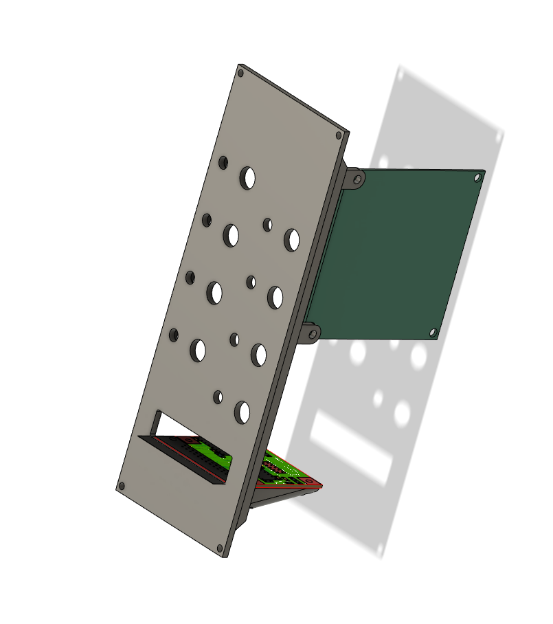
That bottom shelf supports the line driver receiver that will connect this to the midobox with a DB24 “printer” cable. So it needs to be pretty strong. I’m also goign to add a USB port under it just for 5v out to power the sequencer. And I need to figure out of my spacing on the switches is usable or not since they’ll need to be mounted to perfboard strips as the switches I’m using aren’t panel mount. The components for the line driver boards came yesterday…but even though I ordered the boards themselves from modular addict a few days before ordering the components they won’t be here until Monday. So I’m not in a huge rush on this.
Also ordered another 40 jacks since the companion digital out gate/trigger/sync panels which will suck down 32 jacks between them.
And I still have this Quad VCA and performance VCO waiting to be built. Guess I’ve got my weekend filled
4 Likes
That’s gonna be one blinky module!
4 Likes