I’d be inclined to use a pictogram for this. Avalanche would be a six pointed asterisk (snow) adjacent to a tall right angled triangle (slope) with the hypotenuse side facing the asterisk. Put the slope to the left for avalanche, reverse the image for reverse avalanche.
2 Likes
The funny thing is…when I first put that little pictograph on the panel I had it flipped by mistake with the arrow pointing up the mountain. I “fixed” it without stopping to think that technically it was kind of more correct that way ![]()
3 Likes
Very taken with the panels you’re making. Would love to know more about the 2 colour process.
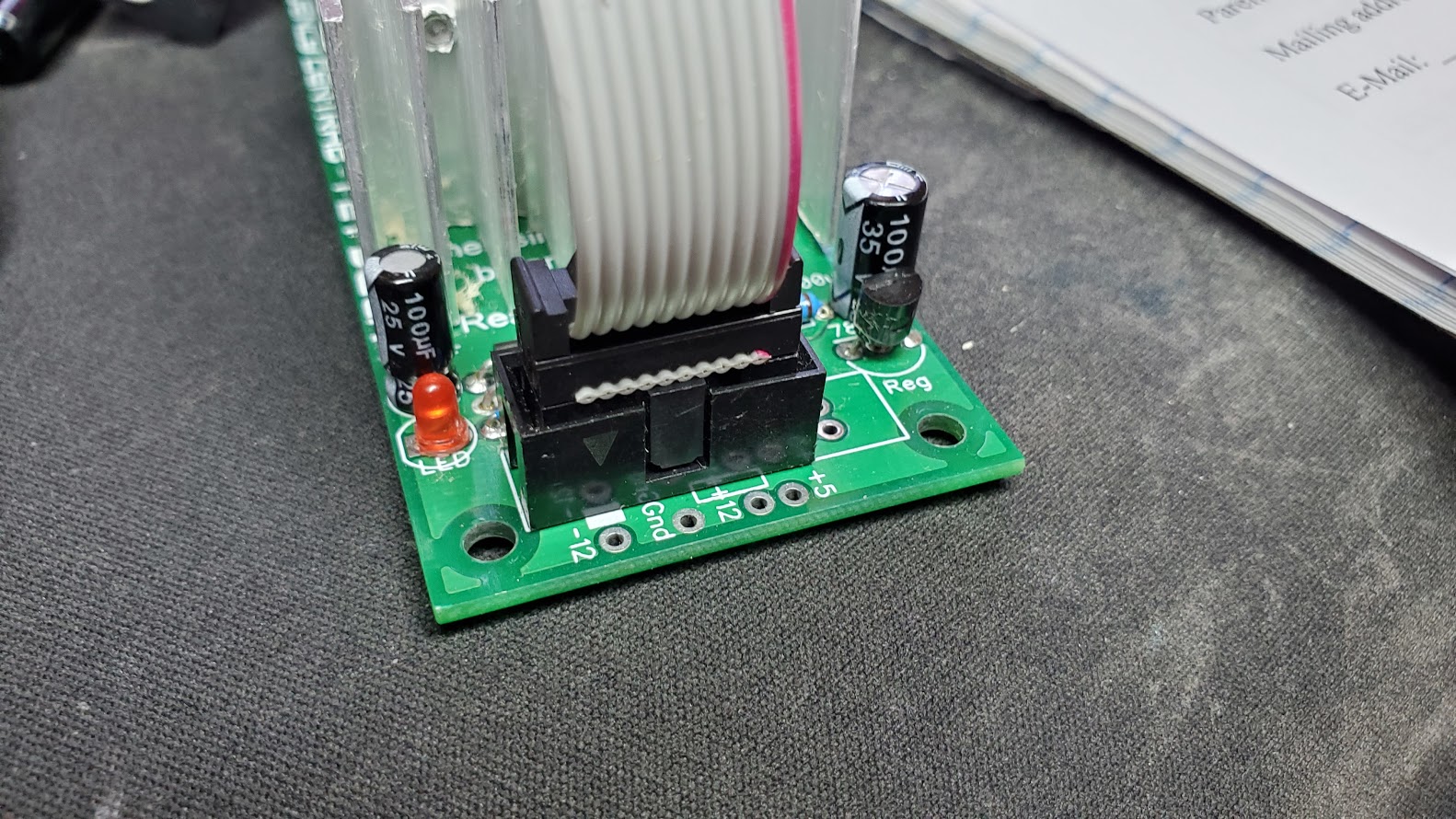
Wondered if you need a hole for the LED as the panel is white? Just put the led in a black shroud glued to the back of the panel.
2 Likes
So say “ehcnalava”…
5 Likes
This approach, maybe?
2 Likes
Looking at your photos and layout, it appears the problem you were having is that you misunderstand how to read a stripboard layout (for very good reason, it’s confusing). Conventionally, the layout shows the components as seen from above on the component side of the stripboard… even though the strips are shown, and they’re on the underside. What you’ve done is to try to build the mirror image of the layout, which works with 2-lead components but runs into trouble with transistors and ICs. See Stripboard building .
3 Likes
I didn’t even notice your pictogram. Too many words on the panel.
1 Like
Yeah, I’m still trying to get my head around stripboard layouts ![]() And that’s exactly what I did. Which probably just makes it more confusing for me since I’m reversing things back and forth in my head. I kind of have an idea how it should work - just…can’t quite get my brain to click it in yet and keep getting mixed up about what side is which when I start building. I’m hoping a few more boards and it will click. Thanks for the link to your FAQ - I had been searching for something like that but kept coming up empty.
And that’s exactly what I did. Which probably just makes it more confusing for me since I’m reversing things back and forth in my head. I kind of have an idea how it should work - just…can’t quite get my brain to click it in yet and keep getting mixed up about what side is which when I start building. I’m hoping a few more boards and it will click. Thanks for the link to your FAQ - I had been searching for something like that but kept coming up empty.
As for the two color printing. I have a Prusa Mk3 with the MMU - so it’s just a matter of setting up a two filament print and hitting go. But the method in that video from make anything achieves the same effect - just with manually swapping filaments. Thankfully there are only a few filament swaps since it’s just the first 2-3 layers. Depending on how thick I made the inlay it’s usually 4 or 6 filament changes.
Basically I design the inlay to be 1mm tall (mostly because I first used this to do white labels on black and any thinner and the white didn’t stand out well. With black on white I could probably get by with .5mm thick since the black has no problem showing up so even a single layer would be fine.) In F360 I do this by embossing the text or image, then extruding it back up as a new body. Then I export the whole design as a STL and bring it into Prusa slicer. There I use “Split to parts” to bring the individual letters out. (one annoying thing about this…you wind up with a separate body/part for each letter or sometimes parts of a letter) Then just assign extruders to the parts to get the look I want.
I just hit me…in this case building it mirrored like I did may actually work out for the best. Since now I can build the other side “normal” (May have to jumper some of the trace cuts I made…but that’s not a huge deal) and the power jack is already in the right spot.
So…for anyone who hasn’t seen this I can just claim I build the hi-hat mirrored on purpose so they can share the common power connector 

4 Likes
It’s a good design. I’ll chip in a concern I have with power headers on stripboard. (It’s been discussed before here - couldn’t find it, honest @fredrik I did look).
The power supply socket has six points of contact for the ground for good reason. When we do stripboard mods to accommodate we need to join them together so that all parts connect to ground and all 3 cables in the ribbon are connected. Discuss…
(God im in a right picky mood today. Apologies to all)
3 Likes
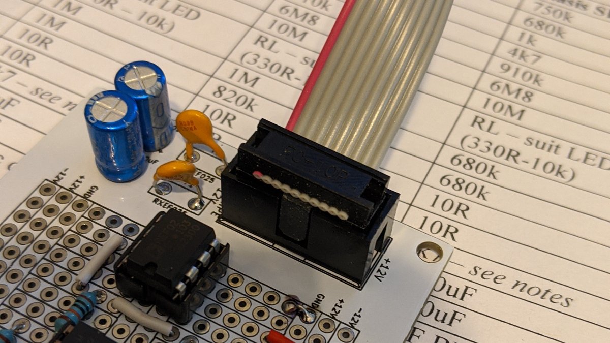
There are 6 ground cables in the ribbon, one per pin, and 2 each for ±12V, and best practice is for all 10 pins to connect to strips and the 3 middle strips to connect together. Looks like you made a strip cut down the middle of the connector which is a step in the wrong direction; should have left the strips intact. (The reason being that each ribbon cable core is rather thin to be carrying the full power current alone. Or, one might better say, the reason is to try to overcome Doepfer’s silly choice of power cable in the first place, but that’s a topic for another thread.)
3 Likes
Good point. This is what I get for doing electronics projects in the last hour or two before bed when I’m exhausted from work, other projects, raising my kid, and all the other stuff life tosses at me. My clouded half asleep thinking was “I’m building two circuits - I need to isolate them from each other” Without stopping to think that - this is power they both need it. Not even considering the current carrying ability of the power wires. (which is a good point…though at least this particular circuit I can’t see the power draw being enough to worry about even with the tiny 28awg wire in the IDC cable.
So tonight before building the second half I went ahead and tied all the grounds together and tied the two sides of the power connector together.

I also marked my mistaken gaps in red and drilled out the new gaps…two of which I goofed on so marked THEM in red and re-drilled. Sigh. One one was an issue that required a jumper at least.
I then Proceeded to build the second circuit “properly” instead of mirrored. Didn’t even forget any jumpers this time!

Lucked out - last nights mistakes didn’t even get in the way:

I did leave out the jumper on the -12v and the two caps on the -12v on purpose. Since this circuit doesn’t use -12v I can’t think of any good reason to have those caps on the -12v line. Someone please correct me if I’m wrong but seems just leaving it disconnected is a better course. (Yeah…they’re still there on the other side…but I’m probably going to remove them from there as well.)
Also realized my missing capacitor values last night was just me half awake mixing up my uf/nf/pf conversions…ugh
Plugged it in…and…I got nothing. Just some clicking when the LFO triggers. Crud.
Ok…let’s hook the first side back up. Uh Oh…still nothing! What the heck…I had even tested the first side again after modifying the power connection…how could it have suddenly died?
After three tries of jumping things back and forth and trying to figure out what was wrong I saw it. Or rather I realized what I didn’t see. Lights on my power supply.
Apparently those darn things work a lot better when you remember to plug them into the wall. ![]()
With power actually applied…woo hoo! They both work!
Though I did find a few other oops from last nights side. Not only did I get confused on what cap values I had…I got really mixed up with which to install apparently. So…need to try some different values on there tomorrow after I get some sleep to see if I can get it sounding a bit better. I think i also mixed up the snare/hi-hat labels…but I’m too tired to say for sure right now - one more thing to check in the morning.
And finally…I installed the LED wrong last night. The anode is one row off. So it’s bypassing the 1k resistor entirely. Whoops. Good thing it hasn’t got a really hot trigger signal. Easy enough fix. I used these clear blue LED’s because I’ve got a giant bag of them from years ago. Still thinking about adding them to the panel anyway. Oh, and I forgot - the question earlier about just putting the LED behind the panel as is…I think the 3mm panel is a little thick for the LED’s to be visible…though just leaving a thin area to act as a filter over them is an interesting Idea I just may have to try. maybe a little pocket behind the “TRIG” label…hmmm.
But…I need sleep. Especially because I big bag from Tayda showed up today and a package from LMNK is showing up tomorrow…so I’m going to have a couple of boards waiting to be soldered up tomorrow ![]() Which also means I really need to get out to my shed this weekend and scrounge up enough plywood for a case…
Which also means I really need to get out to my shed this weekend and scrounge up enough plywood for a case…
Thanks for the feedback, ideas, corrections, and all that everyone! Really appreciate it all!
4 Likes
Sure, no point in connecting and filtering the -12V rail if the circuit doesn’t use it!
2 Likes
Yeah, I kept going back over the circuit thinking I had to have missed something attached to the -12v rail to justify those caps.
One thing no one has yet noticed (or noticed and didn’t point out / was too polite to point out) is that my power cables are backwards. My shrouds are keyed to match what @analogoutput shows on his footprint here: Kosmo Sequential Switch
With the key to the left - is at the top and + is at the bottom.
But…that puts the red stripe at the bottom on + not negative with the pre-made 10 pin cables I have on hand. (which…to me makes more sense having the red stripe on the positive) I’m not sure if this is just the cables I have on hand or if actual eurorack spec has cables reversed from “normal”. These were just cheap cables I got pre-made off Amazon a few years ago to connect sub-assemblies in my sequencer.
Debating if I should make new cables to be more consistent with “standards” - though since I’m only using keyed shrouds for power and the keying is consistent it seems there’s little point in putting in the effort.
Your photo shows the shrouded header with the key on the right side, not the left. Then a correctly made Eurorack/Kosmo power cable will have the red striped edge, which is -12V, on the bottom in that view and +12V on the top, which is correct (-12V connected to capacitor and nothing else, +12V to capacitor and then on to the transistors).
I’m not sure what you’re saying but if you end up with the -12V on the top when you plug in, then there must be something wrong with your cable.
And if you end up with +12V on the top then everything’s correct.
2 Likes
Yeah, I’ve got +12 correctly on the top.
Just the red stripe on my cables is on the wrong side.
My connectors are correct. But my cables are visually backwards. Not that it matters since they’re keyed. But…it still seems to be inconsistent with the defined standard.
Not sure why the pre-made cables would be made that way…it would make sense for the red stripe to go to the marked pin1 with the arrow. But…I didn’t make them so I can’t say why they were done that way.
Just debating when I make more cables to start connecting things if I want to follow the standard or keep things consistent with the handfull of pre-made cables I have that have the stripe backwards.
Go with the standard for all future cables and maybe remake this one. If you ever pick up a eurorack module, they don’t always have keyed connectors.
3 Likes
Well, so much for my weekend plans 
Fedex just delivered me a nice empty cardboard sleeve wide open on two sides, with a crumpled packing list inside and nothing else.
Good thing I’ve got more stripboard on hand to keep me occupied while I wait for Sam or whoever he has managing his store to sort this out.
It’s a decent bit of cardboard…but not quite worth $220 without the boards that should be in it 
3 Likes
UGH! Awful. Sorry to hear that. 
I had a missing package and Sam’s team promptly sent out another.
Yeah, I would remake those cables. Just in case you ever have to power something without a shrouded header.
1 Like