My first DIY modules - starting a Kosmo format build

Oh hey…look what I just found:

Guess I never did build that second MIDI board! And I only see 2 midi jacks in my parts bin (I thought I had more) so looks like I need to buy some parts before I can build it.

And a spare core board, I also have a spare Discovery board for it (Picked it up used at a hamfest for $5) so that’s enough to build another F4 core for a really crazy midi controller, or another sequencer. Looks like I also have all the components to build the core board. (I wasn’t sure if I could replace the 50 pin sockets without damaging the board so ordered the spares to build another just in case.)

So tomorrow night I can take some time and at least decide where I’m going to mount the MIDI boards.

5 Likes

So…I had a “productive” lunch break:

To safely drill the holes for the MIDI boards I needed to completely disassemble it. Which reminds me of some of the annoying things about assembling/disassembling the board stack which I need to improve. And if I’ve got it this far apart and have to engineer and print new parts…may as well also finally redo those button caps and knobs.

I setup a test print on the caps. I suspect all of these are going to be loose. It’s just the old onshape design imported into Fusion. So if I want to modify much of anything I’m going to have to redraw it. Now that I’m not limited by the resolution of the FDM printer though I can and often need to run different tolerances.

I’m also going to need a lot more spacers…some threaded some not. I’ll probably still FDM print those though…they’re not visible and a lot quicker to FDM print. Plus I’ve yet to have great luck with threads on SLA parts holding up to use with most of the resins I’ve tried. And my new printer does small parts like those much more accurately now anyway.

So going to be a few days of 3D printing before this goes back together.

6 Likes

The final stretch always takes the longest! I want to see this thing jamming

2 Likes

First two batches of caps done.

The first 6 I printed straight on the print bed:

The next three I printed on supports:

Both sets had 0 chamfer, 0.2mm chamfer, and 0.4mm chamfer on the bottom edges. The 0.2 and 0.4 are marked on their sides so I can tell them apart after processing.

Photographing these parts is tricky…so is evaluating them. This semi-clear resin makes it even harder.

Note - the 6 on the build plate look shiny - but that’s just because they’re still covered in liquid resin. Once cleaned and cured they have a milky appearance more like the others. Though…there are differences

:

The top row are the ones that were printed with a 30 degree tilt in two directions on supports while the bottom row are the ones printed right on the plate.

Note how much more clear the ones printed right on the plate are.

It’s more obvious looking straight down on them. It’s kind of hard to tell in the photo though but the milkier angled ones are actually smoother.

The ones printed right on the bed the layer lines are level with that. So you can really see the steps on the top - and feel them with your fingertips:

The ones printed at an angle those layer lines run diagonally so wind up with more resolution due to how much resolution the printer has in each axes.

All of them are within my tolerances for use. The chamfer on the bottom definitely helps on the ones printed right on the bed…but the difference between 0.2mm and 0.4mm is almost unnoticeable.

The chamfered ones did fit a bit tighter…but that was mostly because they held more resin inside that got past the brushing and washing These were 3.45mm square inside to fit on 3.3mm square switches. I dropped it down t o 3.4 just to snug it up a tiny bit…but the way I designed these they can’t come off even if they’re loose since they have that lip at the bottom.

I’m probably going to print them on supports. I think I like the results of the angled print better. Though…they take twice as long to print that way so I may not…

I’m not huge on this resin for them either…but switching to something else will mean cleaning machines which is a bit of a pain I’d rather not mess with right now.

I need 58 of these little buggers though. I can print 15 every 2 hours doing them tilted. I can do 24 every 1 hour printing them flat on the build plate. So…3 hours of printing and 4 extras or 8 hours of printing and 2 extras.

Even so I think I’m going to go tilted. Only the tops are visible…and the tops are more consistent and smooth printed at an angle. There’s something nice about the flat ones too…but I prefer the smooth feel against my fingertips from the angled ones.

7 Likes

Decided to go tilted. Ran a plate last night and then while they were curing started a plate of new custom knobs. The knobs were a quick and dirty design - very similar to the existing FDM knobs just with a different gripping surface. Here it is in my slicer:

image

Ran a plate of 8 knobs before bed and woke up this morning to find that I ran out of resin part way through:

Whoops. Oh well. One or two of them printed enough for me to see how I like the feel of them…and all of them printed enough to see how they fit. The fit is ok…maybe just a hair too tight…I can get them on…but it takes a bit more effort than I’d like. So I’m going to open them up from 6mm to 6.1mm before I re-print.

As for the feel. not super happy with them. Which isn’t surprising as I wasn’t super happy with the knobs they were based on :smiley: Just gave it a bit of a fine tuning though - made them 5mm taller and added a taper at the top:

I think I’ll like that more. Waiting on another plate of switch caps though.

Speaking of switch caps…they came out pretty good…fit just about perfect:

My only complaint is I don’t much care for the semi-transparent look of this resin…But I’m curious to see how much light from the LED’s shows up in/through the caps. So I’ll recap the whole thing with these and give it a try before I resort to mixing up a custom color. But I expect I’ll do a custom blue for both knobs and switch caps before I’m done. (And maybe a few in green/red/black for special functions.)

I also mounted the first MIDI board last night…though I’m not overly happy with it:

I opted to use the inner of the two mounting holes and offset it so it stood off from the board a few mm so the jacks should be flush with the outside of the case. Only after doing this did I realize the error in my ways:

The jacks are flush with the edge of the PCB. So pushing it up like this the PCB will have to protrude as well. Unless I trim the PCB down…Hmmm…Will have to think about this one a bit.

Also debating going with even shorter spacers. I used some of my 5mm’s but the jacks are getting further from the panel than I like:

In fact…they’re far enough away that I’m half tempted to mount this board “upside down” so the jacks face the other direction … but I think this direction makes the most sense so will probably stick wtih it. I could shave those spacers down another 2mm though I suspect…

5 Likes

I teased him to go and make some music and he comes back with this! Building a DIY megasequencer and designing and printing his own knobs! :laughing: :laughing: :laughing: I love this community.

3 Likes

Lunchtime update, second set of switches installed:

I’m much happier with them. More consistent, nicer feeling, stay in place better, almost everything about them I love. Except the color/translucency. I don’t like where the hollow sections inside are visible.

I’ve done some experiments with clear resin and while it’s never 100% colorless it can be made clear. The main reason it looks frosty is the resolution of the print. If you put these under the microscope you see a texture that matches the pixel layout from the LCD mask. It can be polished fairly easily to a full gloss. As small as these are I don’t think I want to do that though…just too much of a pain. If I could do it in a vibratory tumbler…maybe.

I am also having a few with fit issues because uncured resin gets stuck up inside the switch cavity. Even though I’m trying really hard to keep that from happening. The print bed gets an immediate wash in “dirty” denatured alcohol. The parts all get a scrubbing with a soft toothbrush, and then I remove them from the bed. Supports still attached they go into the wash machine for a wash in “clean” denatured alcohol - I leave them attached since they caps fall through the wash basket if I remove them first. Once the wash machine is done the supports come off and then they go into a final super clean wash in fresh 91% isopropyl alcohol with an extra brushing of the openings/bottom. Then they air-dry. And finally they get final cured under UV light. But even through all three wash steps some resin stays in the bottom.

I may have too bring out the ultrasonic cleaner and give them a go in there to get those consistently clean…but there are enough that are OK it’s not worth too much extra effort.

I also have all new standoffs in the needed sizes styles printed. Just need to finish tapping the threaded ones. Even printed with threads I find they benefit from being chased with a proper tap before threading screws into them. The LCD’s get the tallest standoffs, almost everything else uses 10mm. But some get threaded where screws have to thread into them - and others are more of a spacer/sleeve and have a larger opening so they won’t interfere with threads.

5 Likes

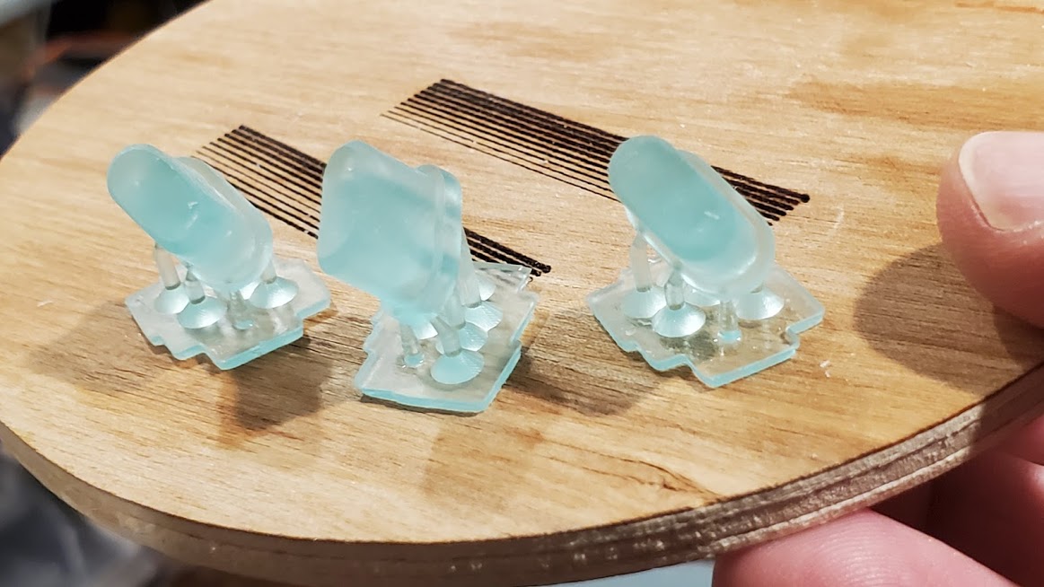
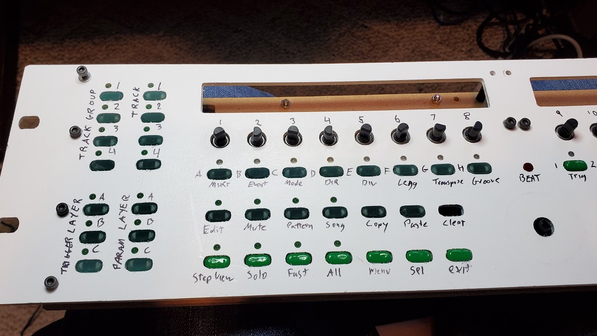
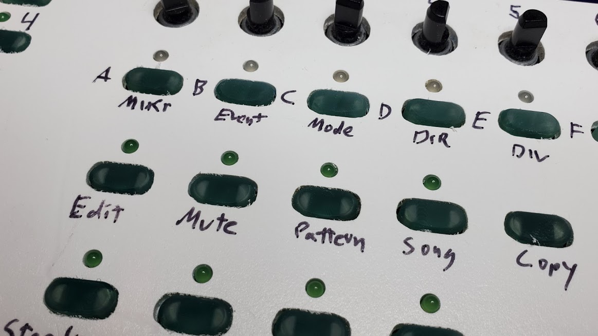
Well, finished the rest of the switch caps yesterday. SO MUCH happier with them than the old ABS ones. They feel so much better under my fingers. This really feels like a professionally made piece of equipment now and not just something I cobbled together. I’ll still wind up re-printing them one more time though because I don’t care for the translucent color.

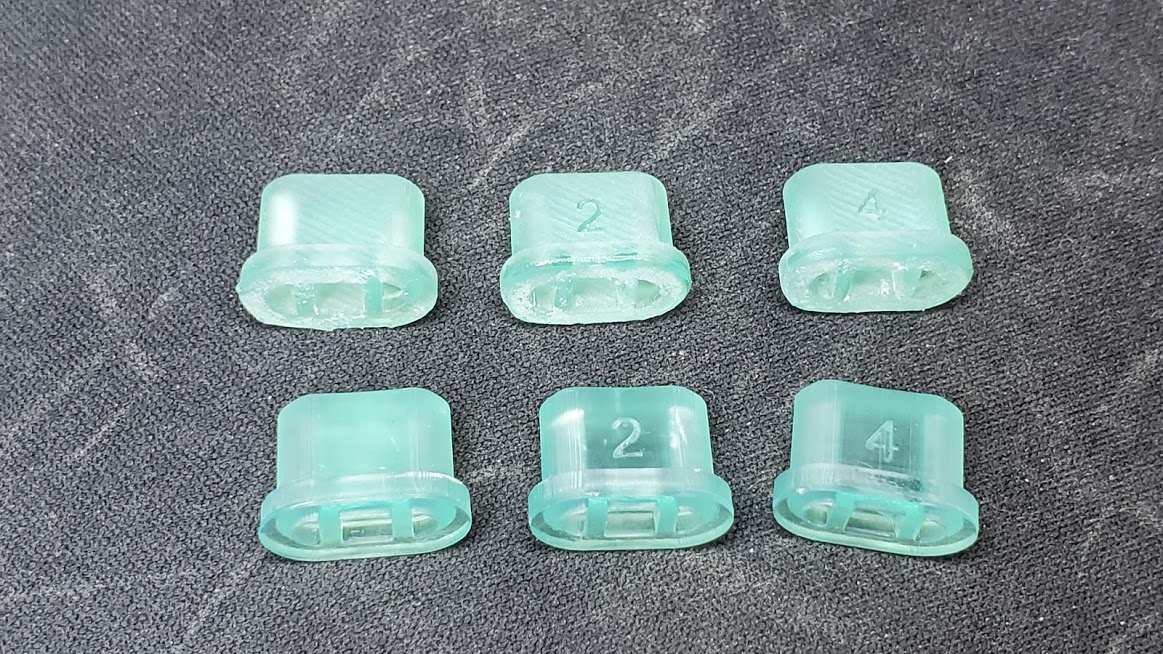
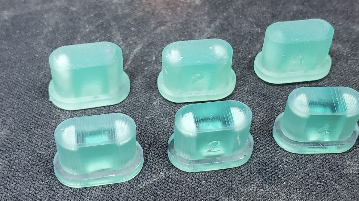
Looking closely you can also see the difference between the first 2 sets and the 2nd two where I added a few minutes in the ultrasonic cleaner as a final cleaning which really did the trick on those inner parts.

Later parts with extra good cleaning - the side holes are visible:

Original parts (top row) with less thorough cleaning - holes aren’t as visible:

I’m also debating what to do for the big scroll wheel. I’m not really happy with the store bought one…it’s too short to grab and the finger impression is too small for my fingers. I test fitted the one I designed as a tuning knob on my SDR and I kind of like it on here:

It isn’t designed for the right type of shaft though so I’ll have to reprint it. I’m just a bit concerned that it may be too much mechanically for the encoder. It’s hollow so it’s not that heavy…but it is quite a bit of plastic to hang off the shaft. I may make it a but shorter…but overall I really like it.

I also did a test to see if the translucent caps pick up any light from the LED’s…as I expected…they don’t.

So I don’t loose anything by reprinting the caps in solid colors. I could reposition the LED’s so they shine through the caps instead of their own holes…but…that would really work best with different switches and that’s more of a redesign than I want to tackle at this point.

With the caps all printed I finished up tapping all of the standoffs and re-assembling it mechanically. My new printer did a much better job on these and I have better quality filament so I basically replaced all of the old standoffs with new ones. A lot of the old ones were breaking or stripped. Now they’re all good. And turns out I didn’t need taller ones for the LCD’s…and I only needed a few non-threaded ones for some special situations.

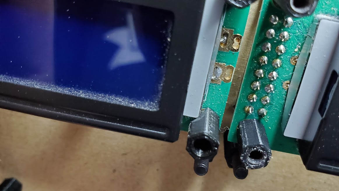
First step is to install the LCD’s. It’s hard to tell in the photo…but they use normal 10mm standoffs on one side…and the other…the cable on them interferes with the mounting so they just rest on a m3 nut and washer:

The tops of the LCD mounts get standoffs on them…but they’re just there to back the front panel - they don’t actually attach to the front panel. And this is where I had to use some non-threaded standoffs because they were too tight of a fit - I even had to shave a few of them down:

Then…I installed all of the standoffs that will support the PCB:

It’s supported in 22 places…and each of those also has a matching standoff that goes on top and either backs the panel or accepts the panel mounting screws. So…I had to print and tap 44 standoffs for this.

I’m not 100% happy with these still…it’s stiffer than it was but could still benefit from a few more. Specifically in the bottom center near the big encoder. I just don’t like the positioning of the holes available so am choosing to be lazy instead of just using one. It also bugs me that I can’t support the main keypad areas evenly. I want to add one more standoff in the center row just to make them more symmetrical - it doesn’t need it…but not having it kind of bugs me.

The photo above has 2 standoffs on each position - but at this point I only install the bottom ones since they won’t be accessible when the PCB is installed so they need to get good and snug now.

The PCB just drops on then and gets held in place with the other half of the standoffs:

It’s a tiny bit tricky getting the PCB on…but if the base plate is drilled accurately it should work. Getting 22 screws to line up at once is very satisfying when it works!

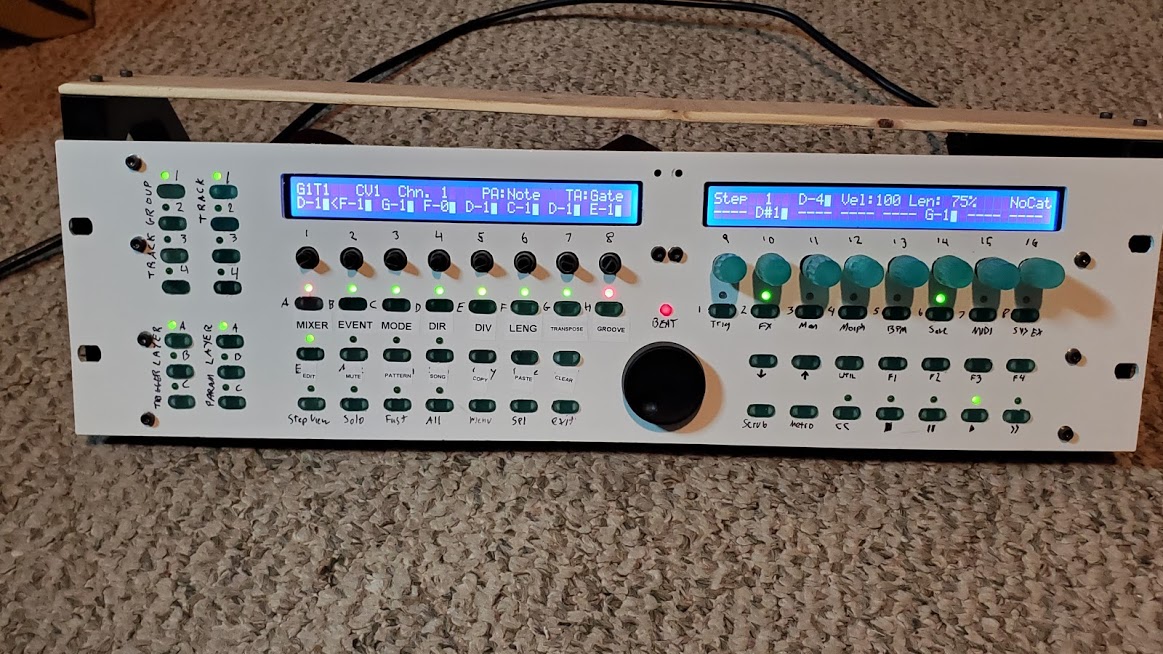
My initial build had some odd stuff going on with threaded and non-threaded standoffs and some that mounted from the front and others from the back. This time I normalized it all. Everything mounts consistently and in logical layers. So once all of the standoffs above the PCB are threaded on the panel goes on:

And the panel is then fastened with 9 small screws from the top. It will be 11 but I didn’t feel like digging out my m3 washers to do the two between the LCD’s. That’s a fairly slow stress area anyway.

I also experimented with using a label maker to replace my chicken scratch…but…it’s really a pain to try and make one label per row…and doing separate labels for each switch is more patience than I posess.

Maybe this weekend I’ll clean off the CNC and cut a new panel from ply…then fire up the laser and engrave labels.

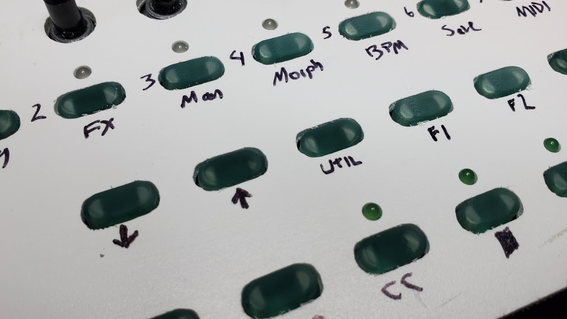
You’ll also notice the new knobs. The ones on 9-16 are done and I’m happy with them. Being a little taller and tapered helps compensate for them being so close together. And the ribbed design gives me a good grip on them despite their smaller size. The 1-8 knobs are an earlier print and fit just a tiny bit too snug to press on all the way. So I need to re-do them.

I’m not really happy at all with the color though. The clear translucent resin just doesn’t do it for me. I just can’t decide if I want to go with simple grey … or color up some custom resin.

But…it’s a LOT better than it was. It’s so much more substantial feeling now and easier to setup and work with.

Tonight I need to cut the opening for the MIDI jacks…and finish my revisions to the power jack mount…then cut a back panel. But it’s very close to “done” as a v2. And gives me some great ideas on how to polish it off for a v3 some day in the future when I decide to make it “just right” :smiley:

6 Likes

Damn that thing looks flash.

6 Likes

Bit more progress on the sequencer to share.

First a look at one option for improving SLA parts in post. Just give them a quick spray of urethane or some other good hard clear finish:

These were all printed identically. The center one has two light coats of spray on water based polyurethane. It’s really hard to get details of this stuff to show up in photos. The color messes with the sensors. But it’s a much more clear and polished look. It almost looks like the ones that still had resin on them right out of the printer. A few more coats and it would be super glossy. It’s a nice trick for translucent/transparent parts. But…I’m going to do these opaque once I choose a color.

I cut an opening for the MIDI ports…and reminded myself why I built a CNC instead of buying more woodworking tools.

I’m really not very happy with this. I had to cut that slot to clear the PCB. But it looks ridiculous. And the ports are still inset too far:

From behind you can see they’re barely flush with the back plate…I could have skipped cutting that slot.

But…that top plate is supposed to be flush with the top of the PCB support board visible behind the midi board. So…it’s bowing a bit right now. The bottom board shows signs of being slightly too wide…which is causing some of this bowing. I’ve just been putting off taking things apart enough to get to that.

I was hoping to redraw the power/leg assembly and have it print overnight. But got distracted drawing up a PCB instead.

Did take the sequencer and the liven warps out to the living room for a bit of experimentation. Hard to believe that a year ago I had this sequencer - but the only functional synths I had were software synths. Now I’ve got 2 FM synths working (to be fair I had the parts on hand for one of them - the other was a ridiculous splurge), the modular, the neutron, the liven, and a volca drum. Honestly did not expect the past year to go this way :smiley:

6 Likes

for your midi ports, maybe print a trim piece, like a picture frame to transition and cover the cuts

7 Likes

Why didn’t I think of that :smiley:
Though…it still doesn’t help with them being inset more than I’d like.

I’m actually toying with making a new PCB that fits all 8 on one board and shifts them closer to the edge so I can offset them the way I want. Just haven’t convinced myself that I want to put THAT much effort into it yet :wink:

5 Likes

The frame might disguise the fact they are inset “too far” too since it will have the varying depths.

1 Like

Also wondering if you could 3d print some soft edging to surround the holes you make. I use a mix of wood glue, wood filler and a drop of water when i need to protect a guitar hole but I have used cut to length edging to stop heavy switches applying pressure to a finish.

3 Likes

Just have to say, your affinity for experimenting with variations is inspiring!

4 Likes

Thanks. It’s something I’ve had to train myself into. I generally hate having to do things over and over…but have come to accept that it’s the only way to figure out exactly what works sometimes.

The past few days I’ve been thinking about the labels and front panel…had an idea yesterday finally. Since I have so much detail I can do with the resin prints…why not do the labels as part of the buttons? Will there be enough detail? Let’s find out!

Easy enough to model with F360’s new emboss tool - just make a sketch with the text and then emboss it 0.8mm deep. (0.8 is how thick I make the labels on my 3d printed panels so they get two layers of filament…not sure how deep I need these to be so just stuck with that same amount.

I had to shorten the inner gaps a bit to clear…but that was also easy:

image

Then changed the text and re-exported for the first 15 caps…loaded them into the printer…and gave them a go in plain grey resin:

That worked far better than I expected. They don’t feel any different when pressed on…and the text is actually mostly legible even on the long ones. But the legibility can be further improved with a bit of laquer stick. I only have white right now (black would probably look better against the grey) but let’s give it a try:

Ok…that’s pretty good! I’ll have to fill the rest of these tonight and install them to see how they look in practice. It’s a lot more tedious having to make each cap individually…but it may solve my labeling problem.

And before I print all of them again…need to finalize my color decision.

Also this lacquer stick apparently works best when you apply it…let it dry/cure for a few days. Then go back and wipe off the excess with some solvent. So it’s not going to be a quick job once I do finalize color options.

I can dye resin just about any color. But the lacquer stick only comes in white/yellow/back/red. But I’d prefer not to dye the resin which means even fewer color options…hmmm…white on black or black on white are probably the easiest. Printing in black gives the finest detail and printing in white gives the least. So white text on black caps would probably give the highest quality…I do have a little bit of black left I might be able to test with…

9 Likes

I have been thinking of how I could use my 3d printer on face plates by making a thin lattice with labels and dial marks to glue onto a standard panel for a 3D effect. Much like the overlays you see on some synths. Quick to print but too fiddly? Thoughts please. Thank you.

Tough call. Single layer prints are really tricky unless you’ve got your bed level perfectly dialed in. And even then…pretty floppy and hard to control. Might be worth a try though…all you’ve got to loose is a bit of filament and time!

1 Like

Installed the new caps to see how they look:

Not bad. I like it more than the translucent blue. But these seem to have come out a bit shorter for some reason. And they’re a slightly looser fit…I think that’s because the grey resin washes clean a lot easier than the really thick syrupy viscous translucent blue does. At least…that would explain why the fit is a bit looser…which may in turn explain why they sit a bit lower.

So…before I run off a bunch of these I probably need to tighten the hole up by 0.1mm and make them about 1mm taller.

And order some black resin and lacquer stik so I can try black on white and white on black and see what I like best.

6 Likes

The buttons look great! I agree I think black font would be slightly better

7 Likes