I’m no fool.*
* I mean, not always.
Getting my cabinet together. Have to fix the last top “bracket”. As I never really understood where I would go when I got my very first PCBs (CatGirlSynth Analog S/R, InfiniteMelody and Psych-LFO), I decided to use sheet metal from my job and went for my own standard.
Now the BIG job starts - figuring out where to fix what module to get some kind of order, and also check all modules. Some modules have +/-15V regulators and I must obviously convert them to +/-12V as I have a 12V PSU …
And desperately need to get the Noise-box finished for my grandsons borthday next weekend ![]()
![]()
![]()
![]()
My latest Kosmo module.
Distortion VCF based on
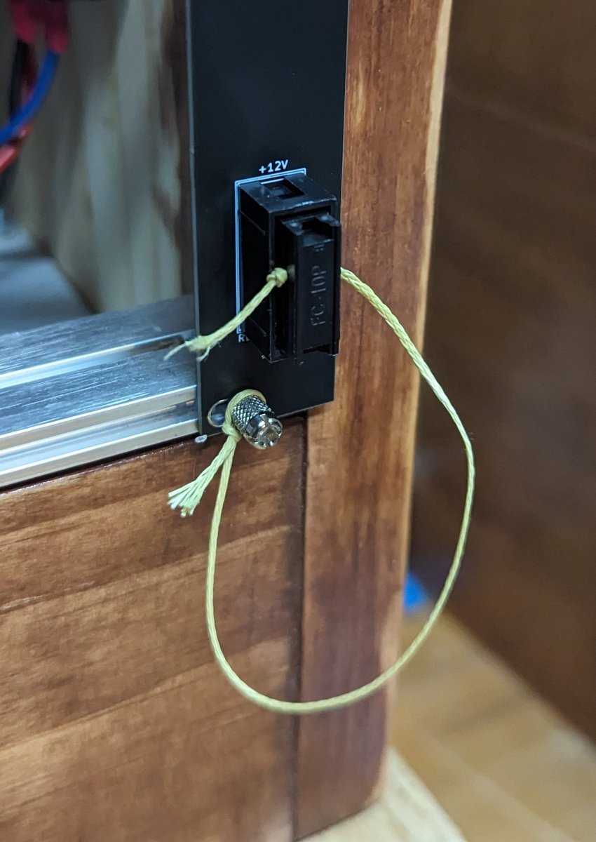
I love a banana set up! How do you handle the ground?
Great stuff!
A good solid back plane connection to ground. Plus you have to ground all expansion cabinets together
Im using a star ground arrangement for all power connections rather than a bus system. And Yes grounds will be shared with subsequent cabinets, probably with a global star ground scheme.
Thanks to @BenRufenacht for saving me the trouble of figuring out how to put a Eurorack Kassutronics Slope PCB behind a Kosmo panel! I just had to remix the style of the front panel (and a tweak or two on the PCB).
Korg MS-20 VCA based on the service manual schematic. No fancy parts needed to get this build! You can find the stripboard layout for this very simple project in the verified stripboard layouts thread.
I’ve finally finished the current batch of modules! But I do have a bit of a problem - the new cabinet which I haven’t even started building is already over 3/4 full…
I already have a YuSynth ADSR which suffered from the ‘not returning to 0V’ problem. That’s fixed with a diode in the output stages, but I thought I’d try a different circuit for this second ADSR - hence the MFOS design.
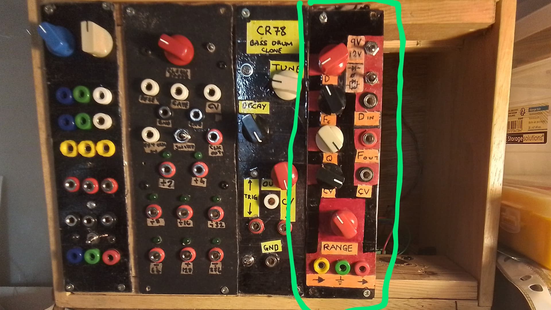
Based on the Pittsburgh Modular VILFO design. I didn’t like the lack of buffering on the outputs, so I added buffers and also a pulse wave output. The circuit generates a pulse wave, so why not have access to it!
Found right here! Built with ferrite beads on the power inputs and without the crowbar diodes.
I like this VCF and built it quite a while ago, but it got pushed out of the cabinet to make space for an MFOS VCF with voltage controlled resonance. It’ll be nice to have it back.
Originally inspired by Hagiwo’s dual quantizer, this has 4 5-octave output channels using a MAX5175BAUD quad DAC and flexible trigger generation options. It uses an I2C EEPROM to store the configuration. The schematic, PCB layout and RP2040 zero code are on GitHub.
Based on two copies of the CGS18 drum simulator. One board uses the original R/C values for high and low toms, the other is tuned to give a bass drum and wood block. I ignored the instruction to use 100k trimmers for the resonance; instead by experiment found padding resistor values (R1+10kPOT+R2 = ~100k) so the panel mounted pot at maximum sets the resonance just short of sustained oscillation. This allows each drum to be adjusted from very dry to highly tuned and resonant. I also (at the panel design stage) added a mixer so some or all drums can play through a single output.
Based on the CGS Voltage Controlled Slope Eurorack with two copies of the PCB behind the panel. I tweaked a few things in the design. By default the circuit can’t be retiggered until the rise/fall cycle is ended, but that’s controlled by just one diode. Including a switch in the circuit for that diode allows the circuit to be retriggered during the fall stage. The CGS circuit already generates a !END circuit using the spare LM3900 op-amp, so I added resistors and zeners to make these outputs available on the panel. Output voltages are set to be compatible with Eurorack by appropriate adjustment of the level trim and changing the zener diode values on the END & !END outputs. The CGS circuit uses DPST switches to enable the exponential rise and fall feature. I changed this to use a DPDT centre-off switch, with the feedback enabled in both ON positions but the 1M resistor to -12V only enabled one way. This gives two different exponential rates. Finally I added (as a behind the scenes dongle) a PULSE output based on a simple op-amp comparator driven by the main OUT signal.
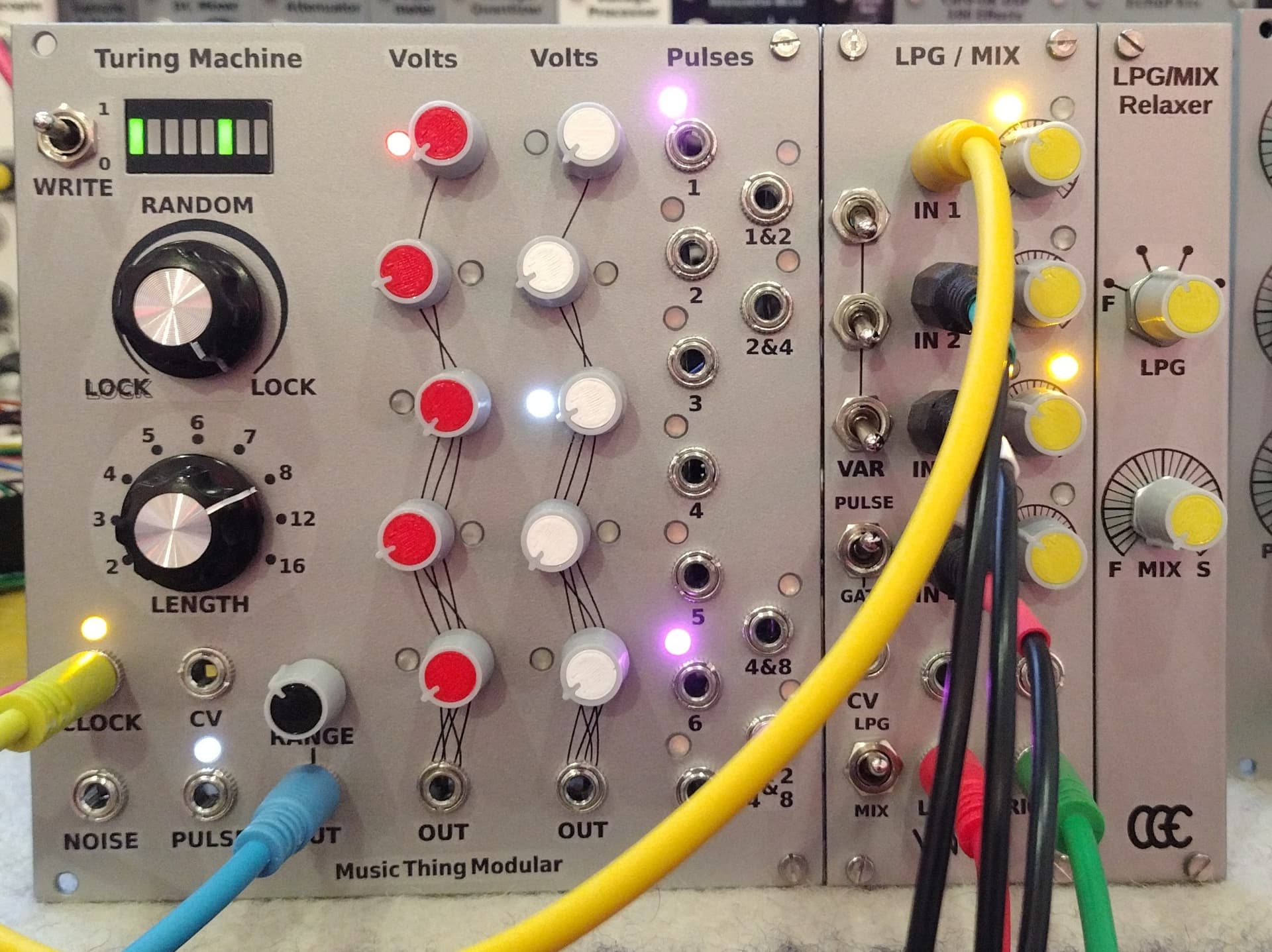
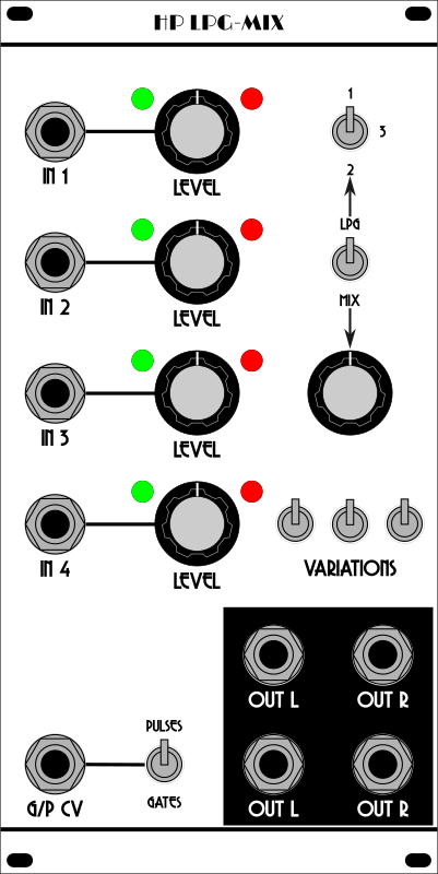
I really like these modules - hence two of them! The second machine has my modified LPG/Mix expander with the Gates/Pulses selector. I’ll be adding a small daughter panel to this to allow control of the vactrol decay time in both Mix and LPG mode. If that works as well as I think it will, I’ll modify the older Vactrol Mix to also allow Mix or LPG mode with variable decay time plus Gates/Pulses switching - it will just lack the three variation switches.
Built from the YuSynth design but without the tone control circuitry. I designed the PCBs to allow additional input modules to be added easily and will almost certainly be adding a couple more input channels fairly soon.
I’ve also got to find space to include a couple of commercial modules (a Limaflo MotoMouth formant filter and an After Later Audio nRings) and a panel mounted Korg SQ-1. Cabinet #3 can’t be too far over the horizon…
Been there, done that, there isn’t a t shirt, maybe I should make one.
Just finished a good old LMNC Filter …
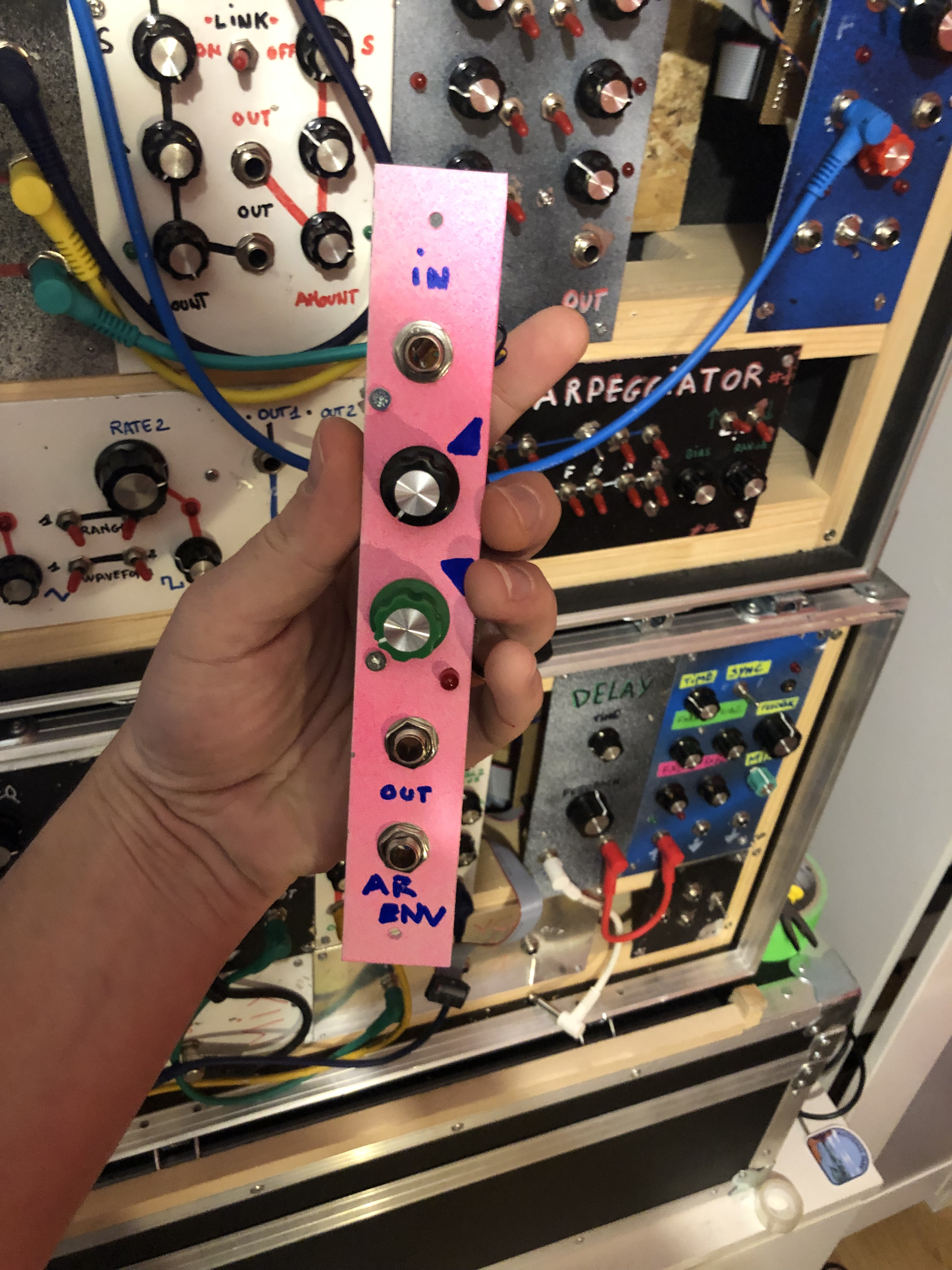
And also a very simple Envelope Generator with a LM386
(original : https://synthnerd.files.wordpress.com/2016/04/op-amp-ar.jpg )
I just changed few stuff to get a small attack and a long decay.
You mean LM358 obviously. I read LM386 and I was like “darn can you really do that with a 0.5watt power amplifier IC?” ![]()
I had exactly the same thought!
Yes you right ! my bad ahah
Always mixing all those numbers
And now let us hear the thing!
B.t.w. I see you are using those ‘standard’ mini jack cables. Would you recommend those?
I will record a jam soon for sure! The mini jacks were purely economical for me. The first modular project I built is a As3340 (it’s in my prototype plastic shoebox goovebox) and when I started shopping for the supplies I realized the cost of using 1/4 in sockets (this one has 8 jack sockets alone) and cables for the much bigger rack I hoped to build was going to be significantly higher than I initially thought. Minijacks and cables were a strategic move to get the project moving with enough steam to keep it moving. I’d probably be a few months away from finishing it for lack of funds available each month. Also, I wanted smaller panels and smaller rack dimensions than Kosmo, but not as small as Eurorack, so they just have a better fit in the space available while still having room to twist knobs with my big hands and fat fingers. ![]()
![]()
A couple of weeks ago I posted about successful modifications to my Turing Machine LPG/MIX module to increase the vactrol relaxation time by changing two resistor values in MIX mode or two capacitor values in LPG mode. At the end I suggested that it should be possible to use a potentiometer (MIX) or a set of switched capacitors (LPG) to allow variation of the relaxation time. I couldn’t get this idea out of my head, so my LPG/MIX now has a ‘relaxer’ daughter panel -
I’ll definitely be adding a PULSES/GATES switcher to my existing Vactrol Mix along with a relaxer panel.
The optimum values of the capacitors and potentiometer will depend on the characteristics of your vactrols. With my ultrabright red LED / GL5528 LDR vactrols I’m using a 50k dual pot with 5k padding resistors for MIX mode, and capacitor values of 100nF, 47nF, 10nF and 4.7nF for LPG (47nF will be replaced with 33nF when the new caps arrive).
Unfortunately there’s an audible glitch when switching between capacitors but that’s a small inconvenience given the extra flexibility of the multiple relaxation times. It’s possible that a make-before-break switch would reduce this.


