Oh reverb, never change.

6 Likes
If you’ve got lots of parameters to play with, you’re going to need a lot of screens:

Cheers
12 Likes
My build of Multi-Filt-O-Matic (a State Variable Filter = LP + BP + HP) is nearing completion. On the left is the v0.2 version, on the right the v0.1 version.

11 Likes
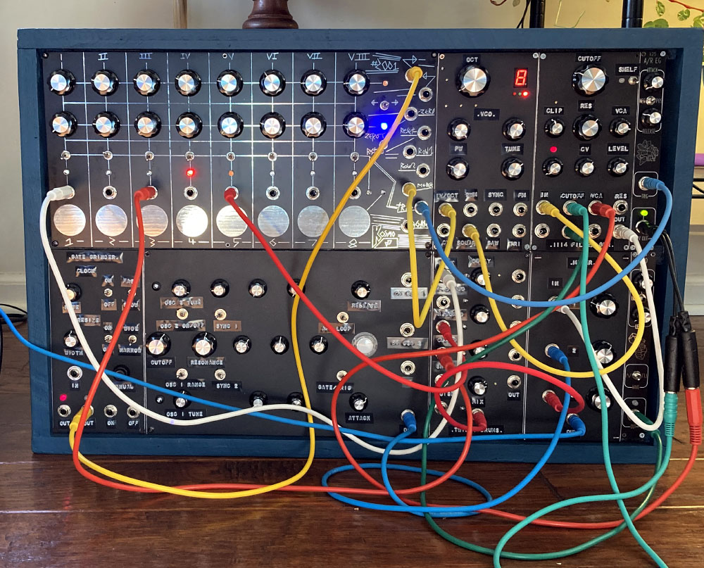
Thanks =) I still need to test it out with a UV light to see the full neon shiny goodness.
And adding in some LED strips on the back/front. Still, it’s bright enough without it haha
Gotta distract from how bad my patches will be XD
4 Likes
yeah I do that with size , lol . looks impressive but I am still trying to make it sound like something other than tortured machines .
2 Likes
I too have built one! It’s dark here, so I’ll post a picture of the 99% completed PCB tomorrow. See the A litany of dumbassery thread for details on the missing percentage.
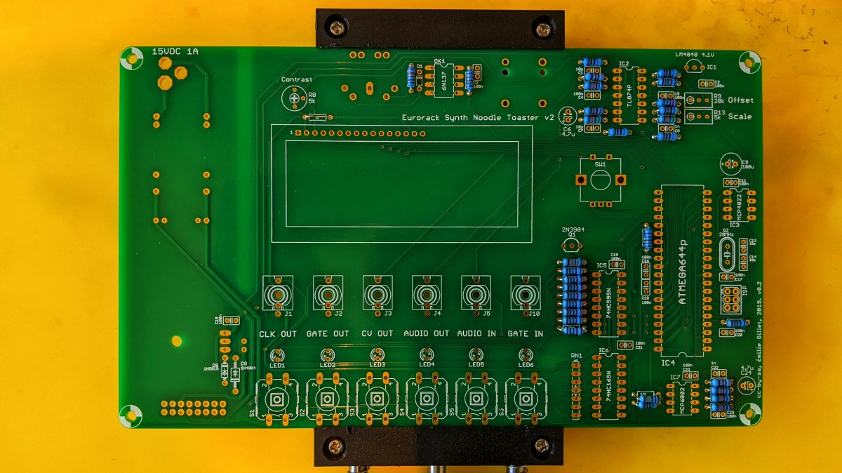
I am also too scared to plug in the PSU and test it. Shirley I now need to build a module tester tester…‽
5 Likes
I gave my brother’s kids the fart box a while back, and since they enjoyed it, I decided to put it into a case where they can expand from that, and I can occasionally rotate in different modules for them to experiment with.
17 Likes
you are the greatest uncle .
7 Likes
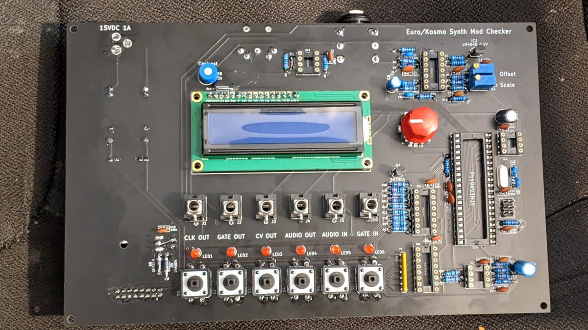
Plugged it in without any chips to see what happened. Checked the +/-12V and 5V pins with the multimeter and they were all correct. Exciting!
Plugged the chips in and powered on again. It lives! ![]()

So I whipped out the Eurorack power breadboard header thing I soldered up the other week and plugged it in. Cue the LCD on the Noodle Toaster displaying cursor blocks and the LEDs on the stripboard failing to light up. A quick check under the PCB, and I’ve only gone and soldered the shrouded header on the wrong way round… ![]()
Tips for how to use de-soldering braid welcomed…
7 Likes
Use flux and that’s basically it ![]() It often helps to put fresh solder on joints first, so that the heat distribution is a bit better. The surface tension of the liquid metal will help to suck up everything with the de-soldering braid. Lay it on and hold your soldering tip on top of it until you the solder transfer to the braid, turning it from copper-ish to silver-ish.
It often helps to put fresh solder on joints first, so that the heat distribution is a bit better. The surface tension of the liquid metal will help to suck up everything with the de-soldering braid. Lay it on and hold your soldering tip on top of it until you the solder transfer to the braid, turning it from copper-ish to silver-ish.
3 Likes
I’ve heard, though I’ve never done it, that you can just use pliers to pull the plastic shroud off the pins and put it back on the other way around.
8 Likes
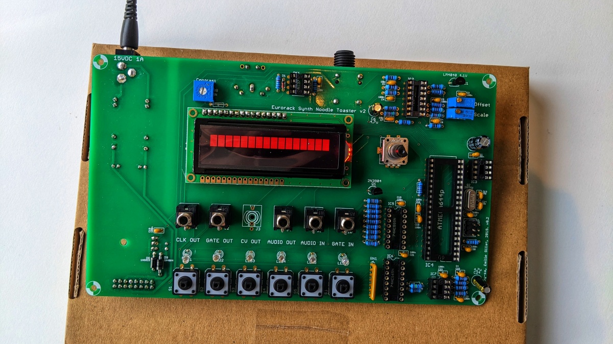
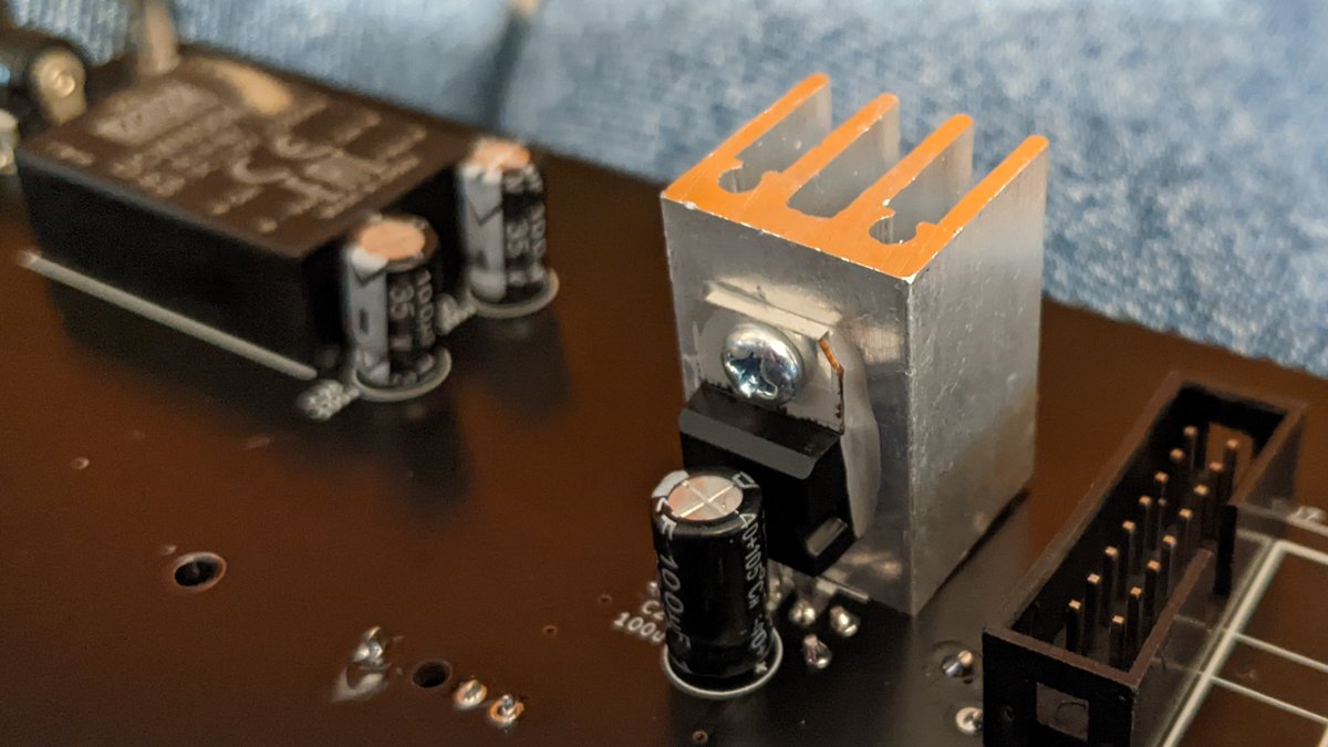
Didn’t even need pliers! Just wiggled it a bit, then gently prised it off with a small flat head, it went back on very easily. I’d never have thought of trying that, and it’s totally saved me from making a right mess. Thanks! ![]()


P.S. I still need to buy a nut and bolt to attach the heatsink. I’m assuming M3 will suffice…?
7 Likes
You likely don’t need to attach it at all, but if you insist, M3 will work.
3 Likes
A dab of heatsink paste helps
2 Likes
Finally decided and created a dedicated “corner”. I need more space, but that’s life ![]() I guess i can put at least two additional cases on top of it:
I guess i can put at least two additional cases on top of it:

17 Likes
For the heatsinks from Tayda, they have an M3 threaded hole, but they need to attach to the side of the L7805 you have up against the PCB.
3 Likes
that looks awesome , wish I could wait for paint to dry lol . nice clean set up should be easy to use .
3 Likes
The trick is to do multiple (paint) jobs in parallel, so that you are forced to wait ![]()
4 Likes
